User Guide
Introduction
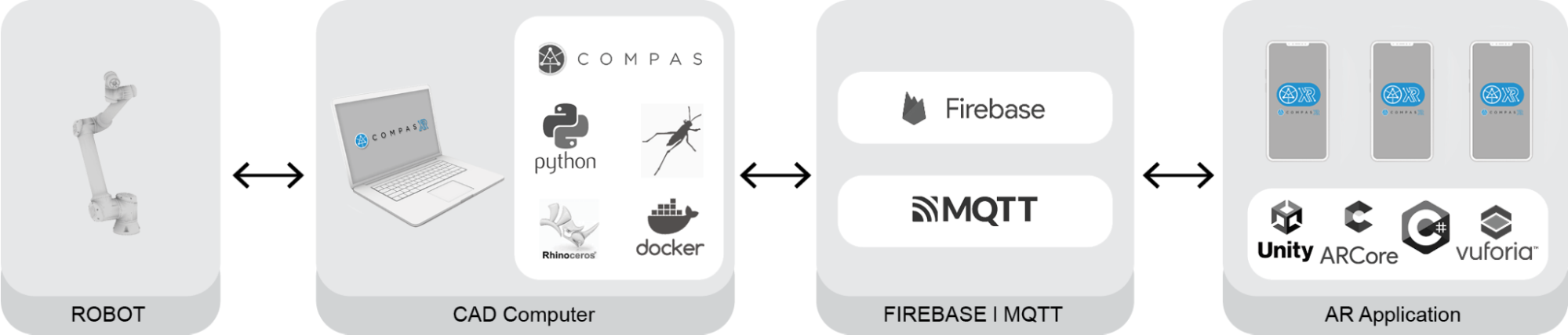
This user guide is here to help you get started with COMPAS XR and understand what it can do. It explains the various features and functions in simple terms and provides straightforward code examples that you can use to create your own models.
Summary of the Workflow
For utilizing the COMPAS XR package for your project, follow these 7 steps:
Assembly Definition: Dependent on the assembly in which you would like to visualize
Database Initialization: Creating and connecting a cloud-based database at Firebase
Data Creation: Types and requirements for various assembly types + Creation of Building Plan and Localization with Frame Positions
Uploading and Visualizing Data: Uploading Data to Firebase and Visualization in Rhino
Define Robotic Assembly Strategy: Toy problem example & Robot Loading (GH & Unity)
Release Procedures: Release .apk for Android devices or ios release procedures (include individual phone builds & Testflight or just a link to how to release to testflight)
User Interaction: Overall Application Progression & UI Overview
Step 1: Assembly Definition
This section provides a quick overview of assemblies. In COMPAS, an assembly is a fundamental data structure used to represent a collection of geometric parts or elements within computational design and engineering workflows. An assembly provides a structured way to organize, manage, and interact with these parts as a cohesive unit.
This section will only provide specific information about assemblies for COMPAS XR. For a more detailed instruction and implementation strategy for COMPAS Assemblies please refer to the documentation for COMPAS Assemblies found here.
COMPAS XR Assembly Information:
Here are some key aspects of constructing assemblies in COMPAS for COMPAS XR Visualization. Additionally, the definition should come from each user depending on the assembly in which they would like to visualize and construct.
Only Assemblies of the Geometry types listed below are acceptable for visualization and assembly:
# COMPAS Geometries that can be used to create assemblies
compas.geometry.Box
compas.geometry.Cylinder

# COMPAS Assemblies that Require .obj export for COMPAS XR Visualization
compas_timber.assembly.TimberAssemblies
compas.datastructures.Mesh
Only assemblies constructed with the processes below allow visualization in COMPAS XR Unity App:
# Import the Assembly, Part, and Mesh classes from the compas.datastructures
from compas.datastructures import Assembly, Part, Mesh

# Import the Box and Cylinder classes from the compas.geometry module
from compas.geometry import Box, Cylinder

# For Geometry Assemblies acceptable add part methods
box_assembly.add_part (box)
box_assembly.add_part(box, frame=frame)
cylinder_assembly.add_part(cylinder)
cylinder_assembly.add_part(cylinder, frame=frame)

# For Custom Meshes, meshes must be added as type Part
part = Part(frame= frame, shape = mesh)
part_assembly.add_part(part)

# For all Box, Cylinder, or Mesh Assemblies made of class type Part
part = Part(name=..., frame=..., shape= GEO)
part = Part(frame=..., shape = GEO)
part_assembly.add_part(part)
NOTE: COMPAS XR Unity is only designed to work with Assemblies that are defined in Meters. If the assembly is defined in any other Unit, it will result in incorrectly scaled visualization on the application side.
Step 2: Database Initialization
Set up Firebase
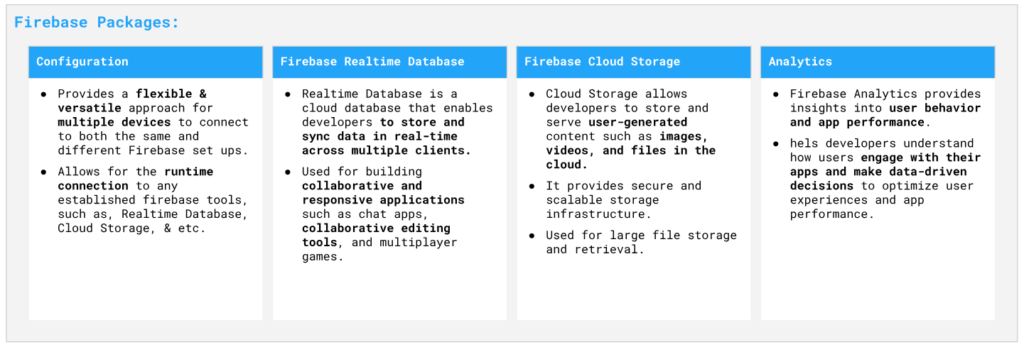
Firebase (FB) is a comprehensive mobile and web application development platform provided by Google. It offers a wide range of tools and services that help developers build high-quality apps more efficiently.
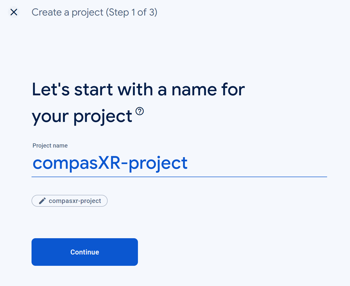
Login with you Google-Account on https://console.firebase.google.com/ and create a new project.
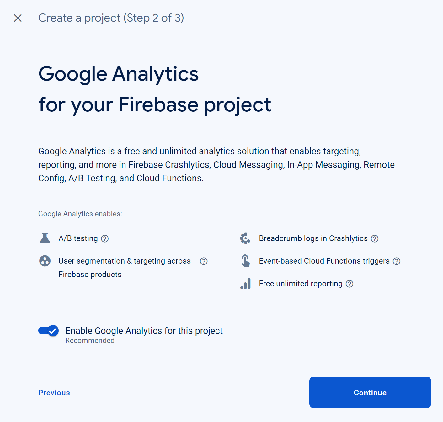
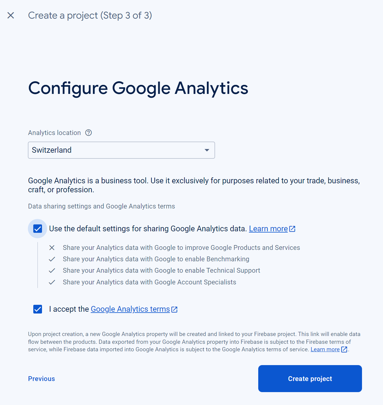
Enable Google Analytics for this project.
Add a Realtime Database (RTDB) and Storage to your project.
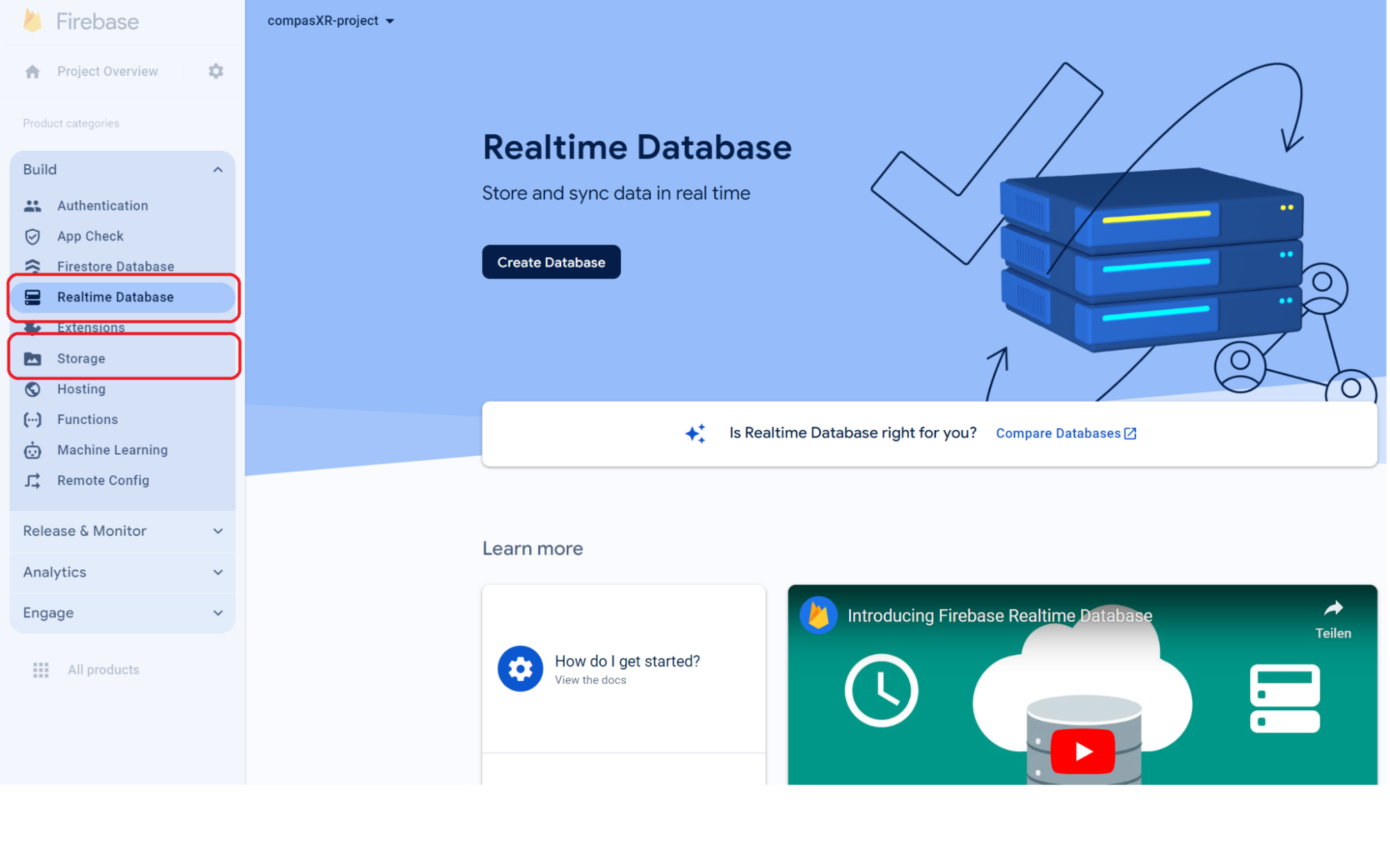
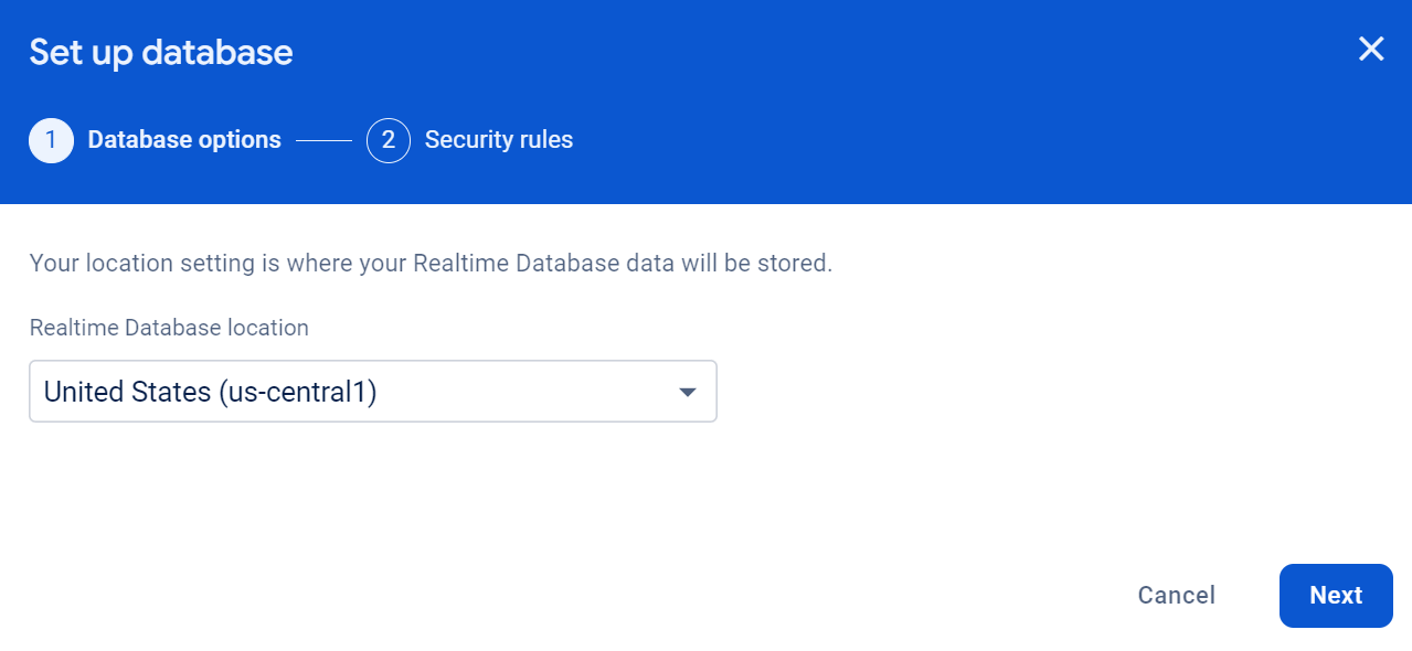
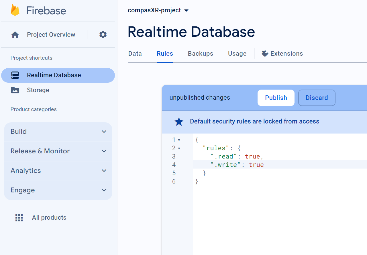
Set up the Realtime Database. This will allow you to store and sync data in real-time across multiple clients.
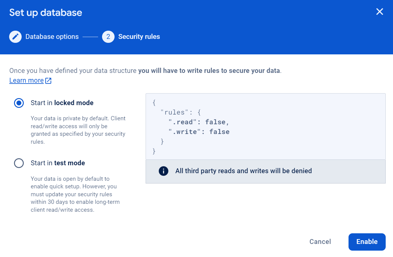
Once the Database is created, search for “Rules” in your Database and rewrite “false” to “true”. Do not forget to publish.
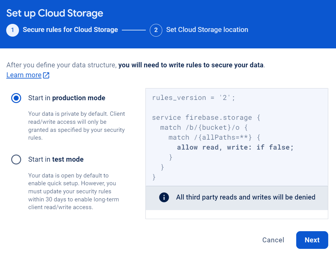
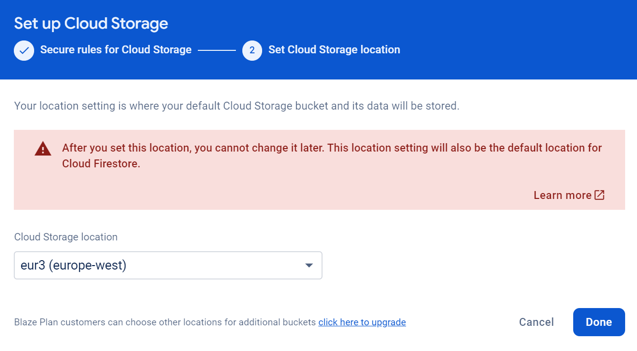
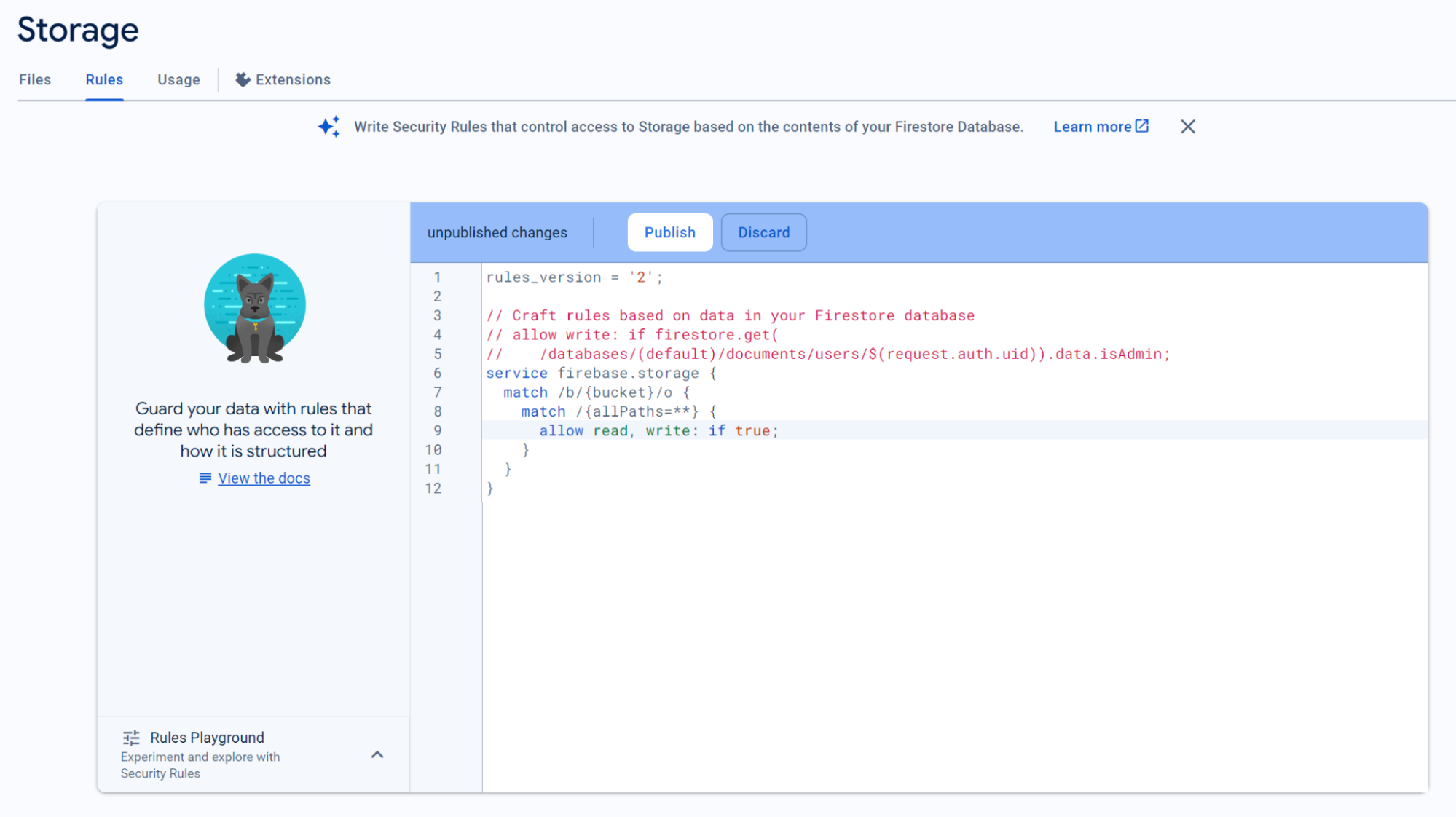
Set up the Storage. This will allow you to store and serve user-generated data in the cloud.
Once the Storage is created, search for “Rules” in your Database and rewrite “false” to “true”. Do not forget to publish.
Create Apps on Firebase
Apps are essential for connecting specific applications to Firebase because they facilitate real-time data synchronization and seamless cloud storage integration. The web app is used for communication between the CAD environment and Firebase, ensuring accurate data exchange. Additionally, the Android and iOS apps connect specific device types to Firebase, enhancing collaboration and improving the overall efficiency of data management across multiple platforms and devices.
Go to your Project Overview, now we create the apps.
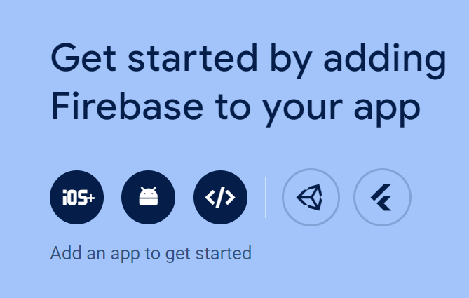
First we create a web app (</>).
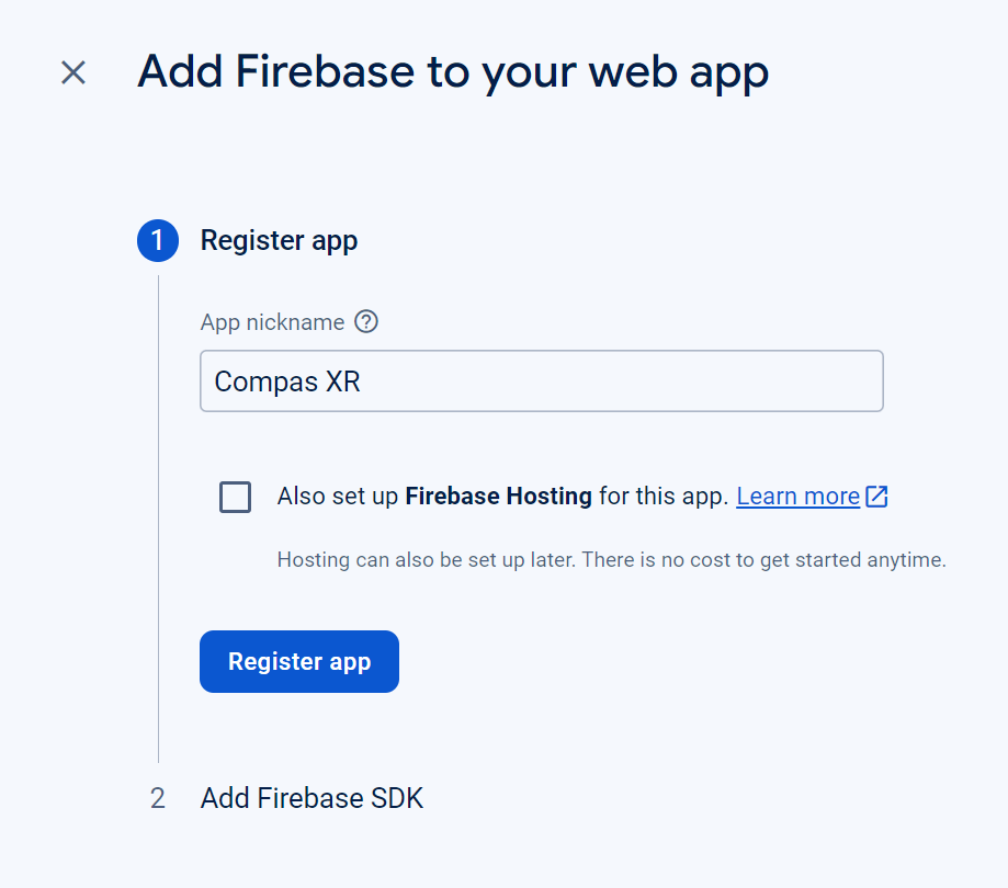
We can access this data later as well.
Now create an Android App with package name com.ETHZ.yourappname
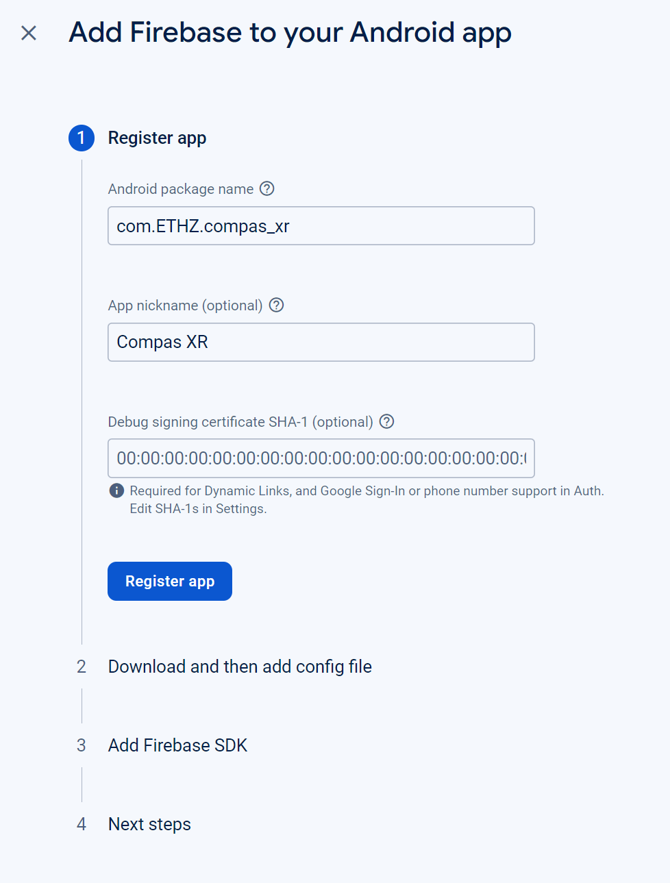
Download the .json file and store it somewhere safe.
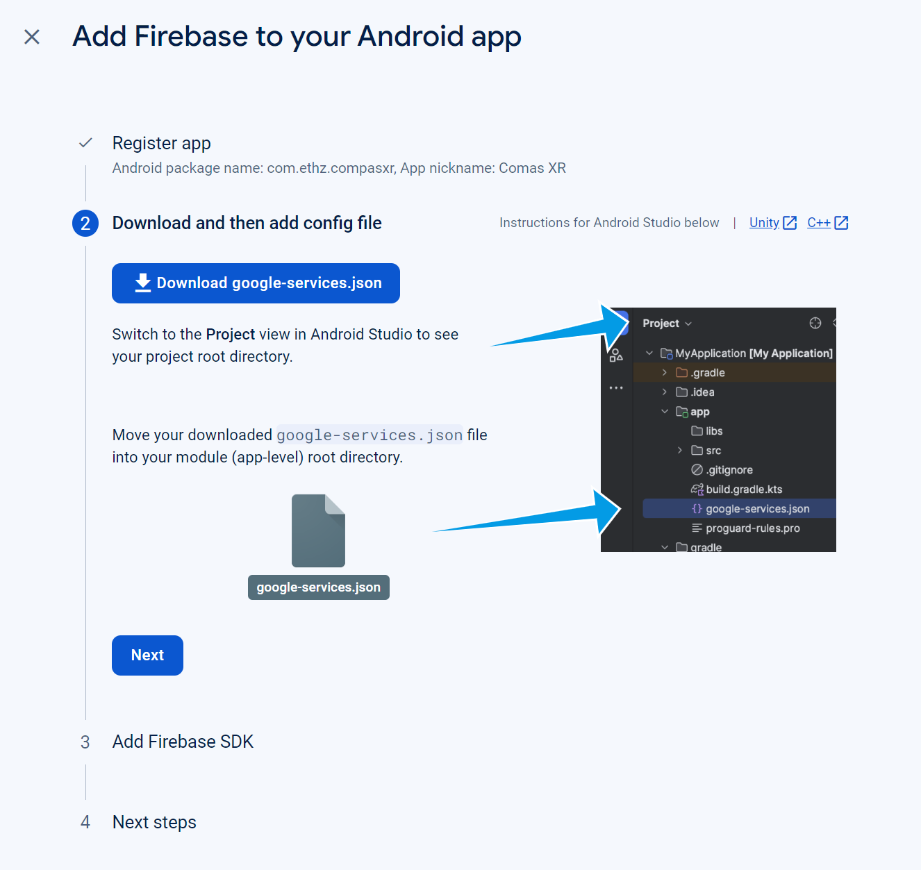
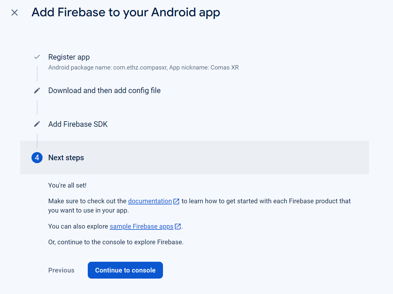
Proceed with the process.
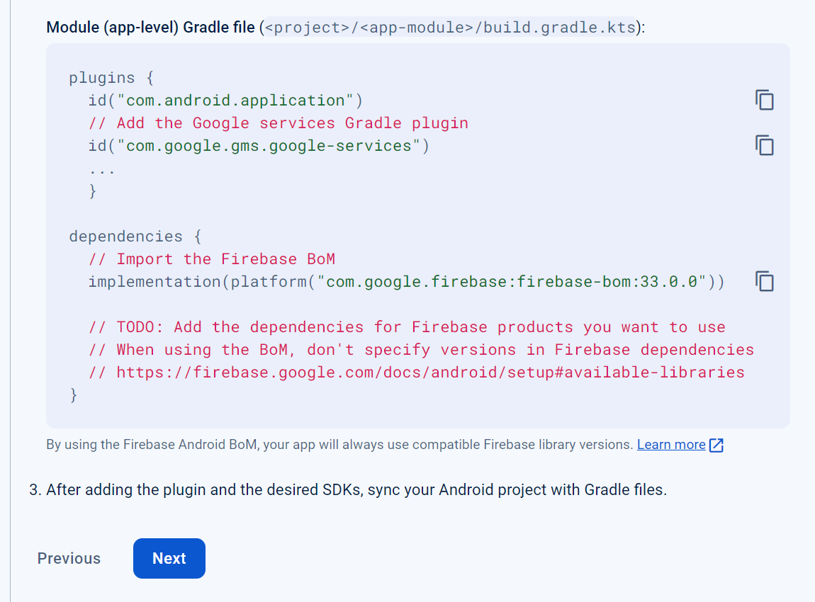
And continue to console.
Connect Grasshopper to Firebase
It is imperative that we connect Grasshopper to Firebase to enable real-time reading and writing of COMPAS data to a cloud-based database. This integration ensures seamless data synchronization and accessibility, both during active sessions and before app start-up. Additionally, it ensures that the information for planning and visualization of assemblies in the CAD environment is accurate to the current assembly processes.
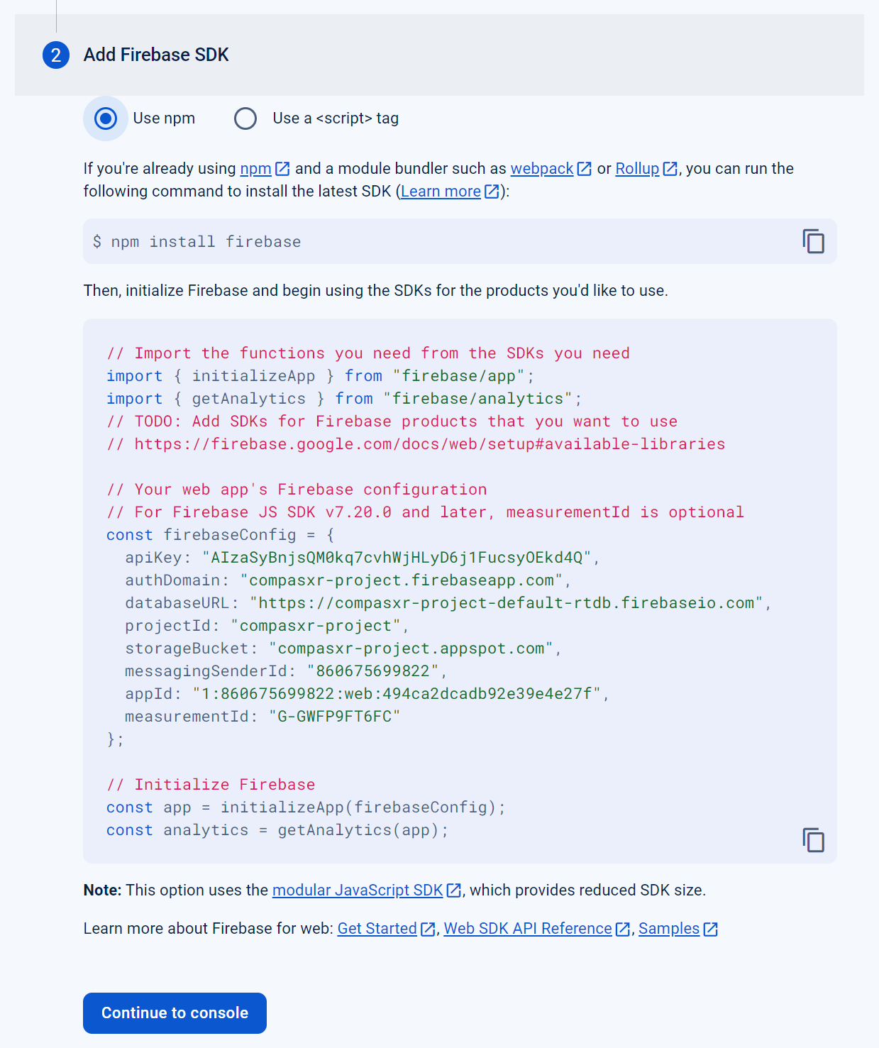
Now we need to Navigate to Settings -> Project Settings -> Your apps -> “Your Web AppName” -> “firebaseConfig”.
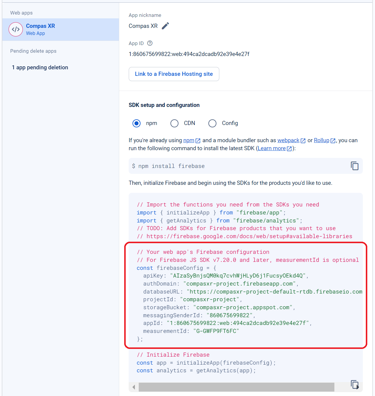
Insert the data into grasshopper to connect with firebase (api_key, auth_domain, database_url, storage_bucket).
For filepath, create a directory in which you would like to store the firebase config information as a .json file type.
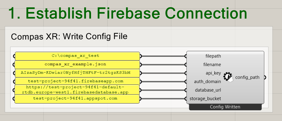
filepath: string (A directory path at which the custom firebase configuration values will be saved.)
filename: string (Optional - An optional file name for firebase configuration files)
api_key: string (A Unique identifier for Firebase project requests.)
auth_domain: string - A domain for firebase user authentication.
database_url: string - The end point for Firebase Realtime Database access.
storage_bucket: string - The end point for Firebase Cloud storage file uploads.
Step 3: Data Creation
Generate Building Plan
COMPAS XR utilizes the and requires data structures of both COMPAS Assembly and BuildingPlan. The primary difference in implementation and utilization of both data structures is as follows. The Assembly serves as a data representation of a collection of geometric objects in space. While the BuildingPlan sequentially reconstructs the building process as a list of Steps or actions needed to complete assembly.
Building Plan data contains the order of steps for assembly with additional information for each step, such as: actor, geometry (type), priority, and is_built. The simplest method for building plan creation is to create the building plan directly from an assembly sequence provided through the COMPAS XR library and is demonstrated in the example below. However the Building Plan and COMPAS XR Unity provide flexibility to create building steps from assembly parts in any sequence order as long as all steps have the complete information as seen above.
# Import the BuildingPlanExtensions class from the compas_xr.project module
from compas_xr.project import BuildingPlanExtensions

# Initialize an instance of the BuildingPlanExtensions class
bpe = BuildingPlanExtensions()

# Generate a building plan based on an assembly sequence
building_plan = bpe.create_buildingplan_from_assembly_sequence(assembly, data_type, robot_keys, priority_lists)
NOTE: While this will generate a usable BuildingPlan, the sequence will be a direct result of the order of assembly will be dictated by the order in which parts were added to the assembly. Additionally, robot_keys & priority_lists inputs are optional inputs that are assembly specific. If they are not input directly by the user, by default each steps actor will be assigned HUMAN and priority will be assigned 0.
assembly: compas.datastructures.Assembly or compas_timber.assembly.TimberAssembly
The assembly a user would like to create a building plan from.
data_type: int (The type of geometry from the input assembly)
0 == Cylinder (Assembly made of cylinders)
1 == Box (Assembly made of Boxes)
2 == ObjFile (Used for TimberAssemblies && Mesh)
robot_keys: list of str
A list of assembly keys that are intended to be constructed by the robot.
priority_lists: list of list of str
Priority lists are used to represent parallel tasks.
The overall list represents the order in which parts need to be assembled.
The internal lists reprepresent parts that can be built in parallel within the overall list
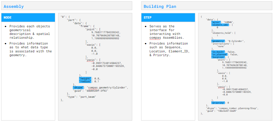
Assembly Data Structure Example Diagram
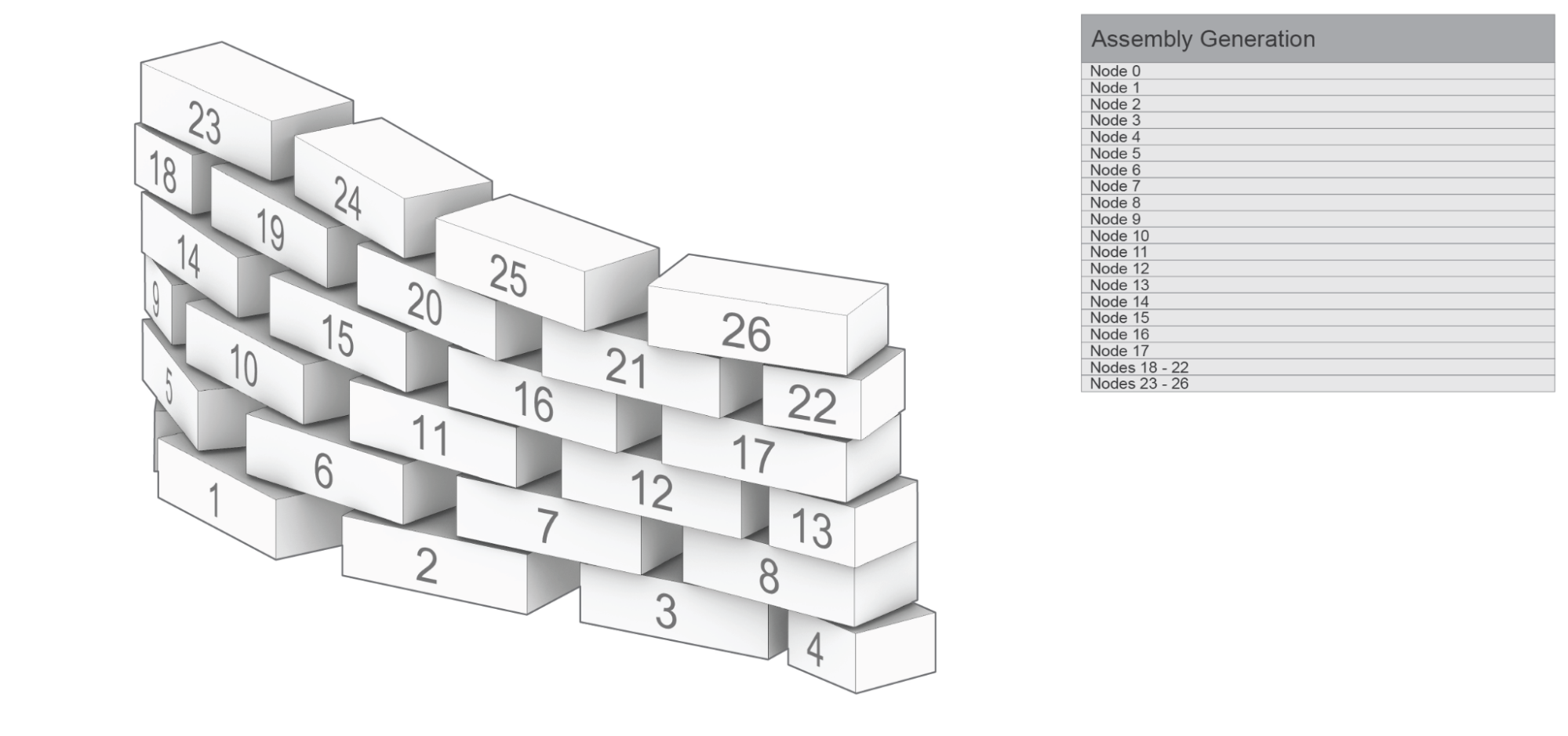
NOTE: The Assembly Data Structure is used to provide geometric, and locational information for a collection of objects in space. It is used as a data structure to provide the information of what is where.
Building Plan Data Structure Example
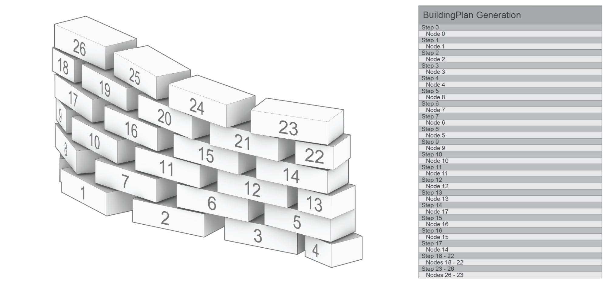
NOTE: The BuildingPlan Data Structure is used to provide topological information that is used to coordinate, distribute, and coordinate the building Process. Information such as actor, is_built, and priority. Additionally it provides the opportunity to resequence elements from the Assembly model into logical sequential building processes.
Building Plan Priority Illustration
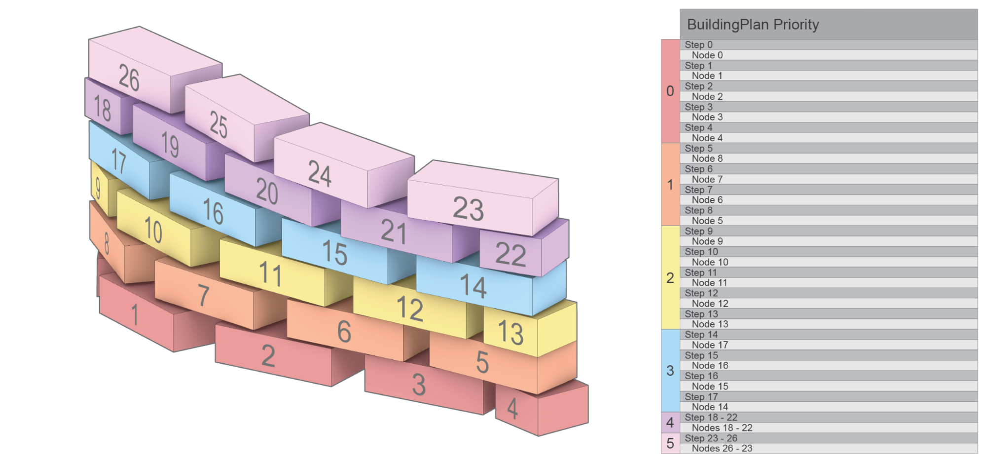
NOTE: Describes a hierarchical relationship of what steps are allowed to be completed in parallel. While the sequence of the assembly has a defined order the priority list establishes allowable methods for deviating sequence order during the assembly process. Additionally the application will prevent you from building, or moving on to a new priority until the current priority is completed.
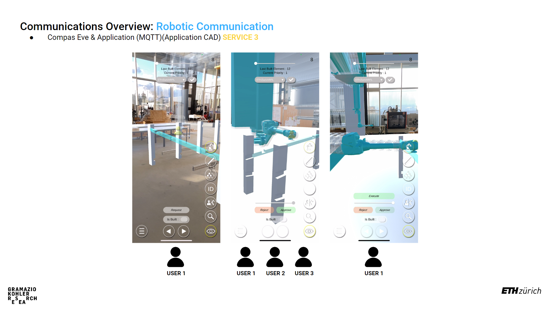
Building Plan Multi User Interaction
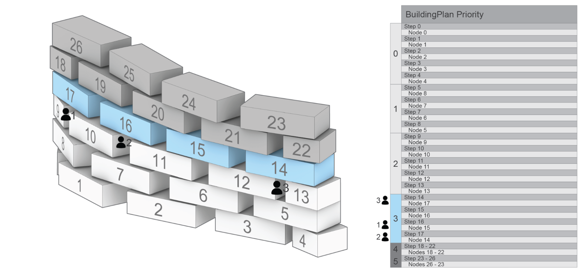
NOTE: Describes a hierarchical relationship of what steps are allowed to be completed in parallel. Priority lists provide avenues for multi-user interaction, by allowing each user to complete a building “Step” within the same priority. As shown in the example above, Priority groups 0, 1,& 2 are completed. While Users 1 through 3 are all working on individual tasks 14, 16, & 17 in Priority group 3, and they are prevented from working on Priority groups 4 & 5.
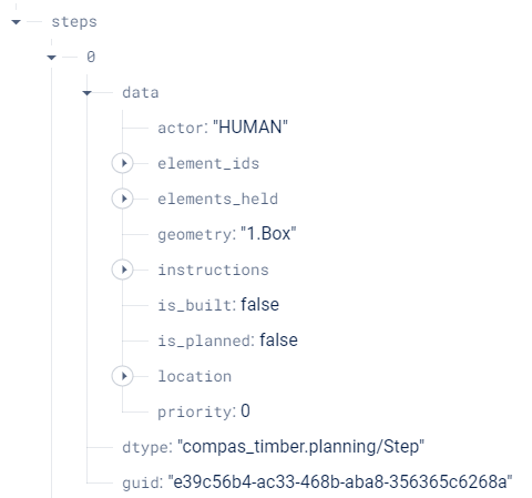
Example of a step within the building plan as it will appear in your firebase Realtime Database:
Set Localization Frame Positions
Localization information is required to establish the position of a virtual object in the real world based on the observed image. This is used specifically for each individual tracking image within the application. Additionally the relationship is constructed through the creation of compas.geometry.Frame objects that exist in relation to the assembly structure.
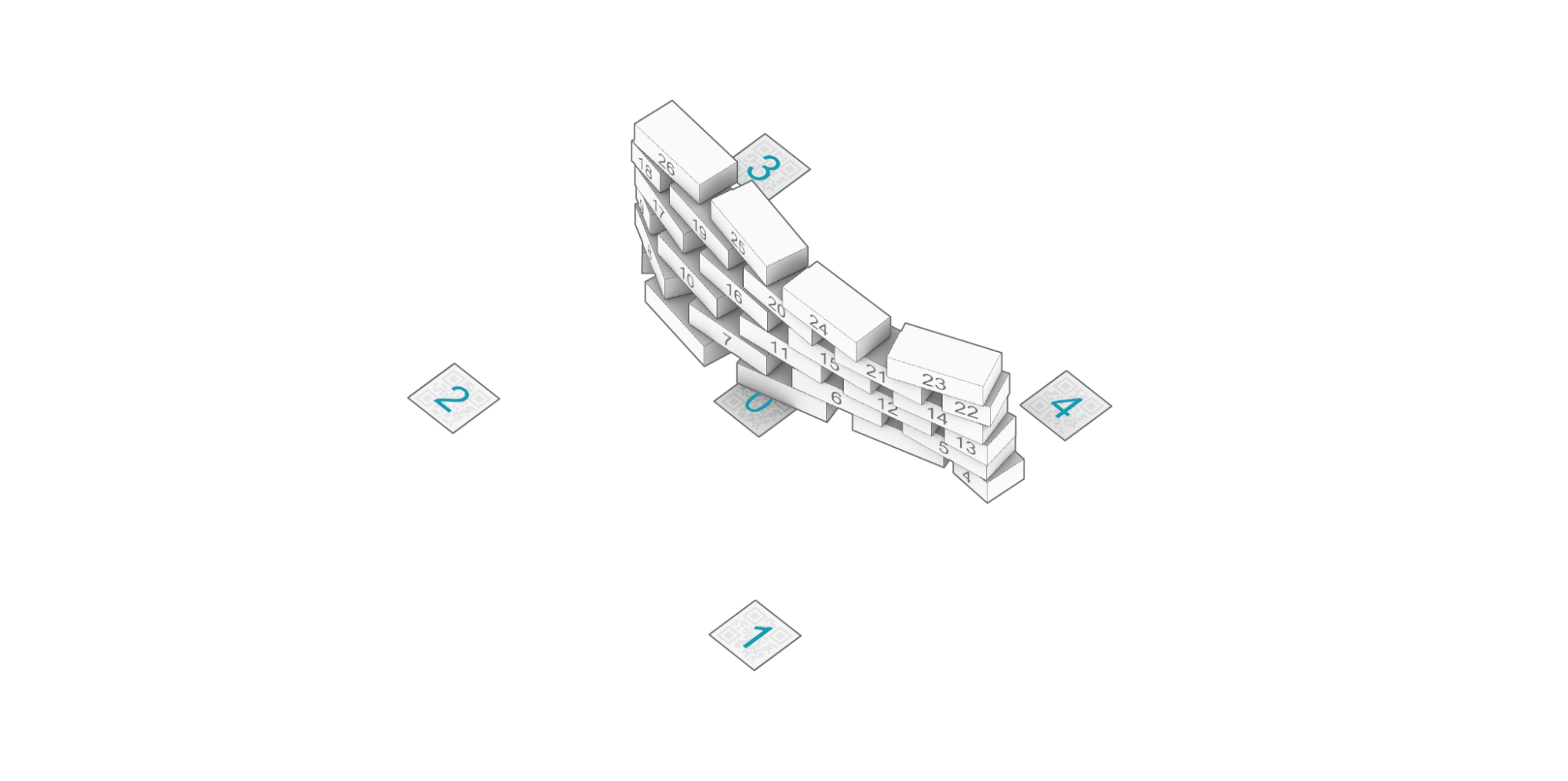
NOTE: In order to have accurate localization of the design objects in space, the frame components need to exist in exact relation in the digital space as in real world, and should be measured EXTREMELY accurately for proper visualization of objects in the real world space.
Additionally the order of QR images is determined by the list order upon upload from user, and defines the relationship
in which Images should be placed in the physical space. Also the app does not allow for more then 30 QR images within
a single project, and will only work with the particular images found at this link.

NOTE: The size of the qr image is also required for specific accuracy in visualization, and should be printed at exactly 15 cm x 15 cm.
Step 4: Uploading and Visualizing Data
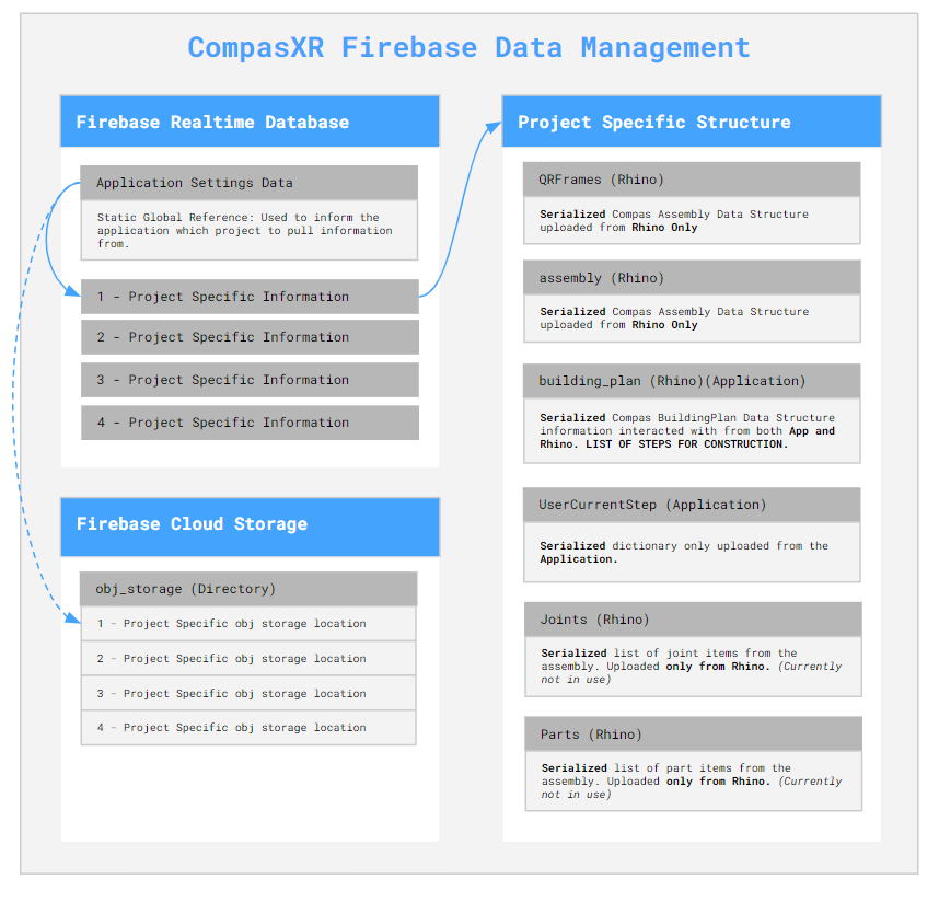
Data Management at the project & application level requires particular attention to specific structure and organizational components required for flexible, reliable, and efficient application functionality. Additionally some of these data structures are only over written via Rhino, the Application, or Both.
Application Settings: Serves as a global constant that informs the application what project specific data to fetch. For additional information see Step 4.3: Upload Application Settings. Additionally the app will only pull information from Firebase storage if instructed by the Application Settings data.
Project Specific Information: All information used to describe one project to the unity application.
Rhino Only Written Information: QRFrames, assembly, joints, & parts Application only Written Information: UserCurrentStep Written by Application & Rhino: building_plan
Step 4.1: Upload to the Firebase Storage (Assembly Dependent)
If you are using COMPAS Timber Assemblies or COMPAS Assemblies made of meshes you are required to export and upload meshes to FirebaseStorage as .obj files. This can be handled directly through the COMPAS XR python library, and can be handled at any point priority to visualization on the application side.
# Import the AssemblyExtensions class from the compas_xr.project module
from compas_xr.project import AssemblyExtensions

# Initialize an instance of the AssemblyExtensions class
ae = AssemblyExtensions()

# Export mesh objects from assembly as .obj files
ae.export_mesh_assembly_objs(assembly, folder_path, new_folder_name, False)

# Export Beam objects from TimberAssembly as .obj files
ae.export_timberassembly_objs(timber_assembly, folder_path, new_folder_name, False)
Step 4.2: Upload Project Data to the Realtime Database
As previously mentioned, project information stored under a specific firebase project name that comes directly from rhino upload information consists of QRFrames, Assembly, BuildingPlan, Joints, & Parts. Additionally the library allows functionality of uploading all required COMPAS class objects.
# Import Project Manager class from compas_xr
from compas_xr.project import ProjectManager

# Define instance of Project manager class with firebase config file path as input
pm = ProjectManager(config_filepath)

# Call upload project data method
pm.upload_project_data_from_compas(project_name, assembly, building_plan, qr_frames)
NOTE: It is key to clear naming conventions for the project name, as it is used to define the information that the application is reading from and provides the only specific reference for individual Firebase projects. Additionally, the project name cannot include any extension of “.” this will signify a file type (ex: .json) and result in an error on upload.
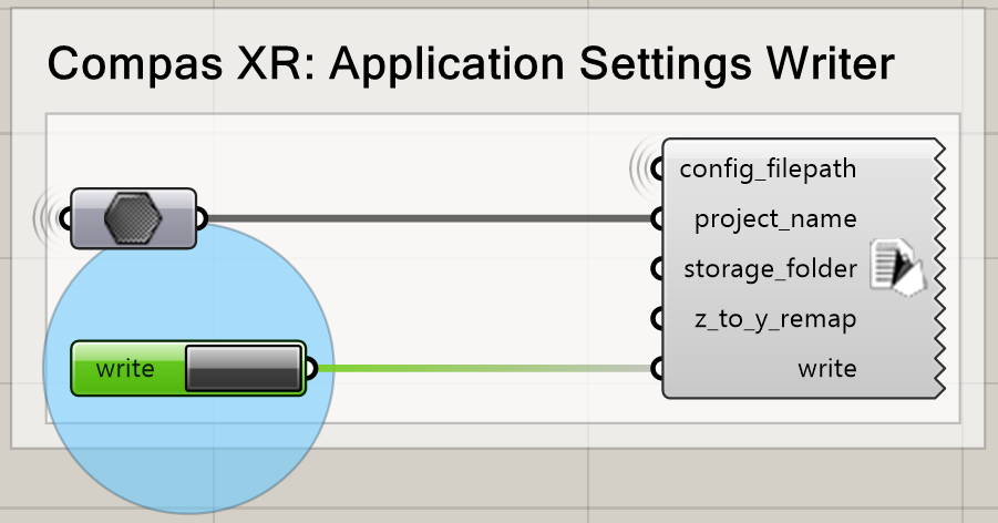
Step 4.3: Upload Application Settings
The application settings writer is used as a global constant that is pulled on the user device every time that the application is started. Additionally it requires a specific structure, and should be written from compas_xr library as follows:
# Import Project Manager class from compas_xr
from compas_xr.project import ProjectManager

# Define instance of Project manager class with firebase config file path as input
pm = ProjectManager(config_filepath)

# Call upload Application settings writer class method
pm.application_settings_writer(app_settings.project_name, app_settings.storage_folder, app_settings.z_to_y_remap)
Example File Component:
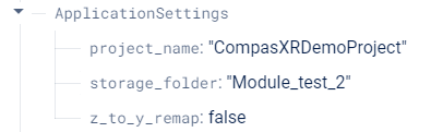
project_name: str - The name in which project data is stored under
storage_folder: str (ONLY FOR .obj files) - The name of the storage folder which the project specific .obj files are stored - NOTE: This is only used for assembly types of TimberAssembly & Mesh (WIP) - NOTE: If no input: default == “None”
z_to_y_remap: bool - If remap is applied to the objects on export or not. - NOTE: Only required for .obj files (TimberAssemblies & Mesh) - NOTE: default == False
Step 4.4: Uploading QR-Frames Data During Assembly Process (Only as needed)
If frames for QR-Codes need to be added to the Realtime Database throughout the building process (Can be helpful in particular assemblies of large scale). Then it should be handled via the compas_xr library functionalities listed below, as the order and data structure of uploading localization information to the database is particular.
# Import Project Manager class from compas_xr
from compas_xr.project import ProjectManager

# Define instance of Project manager class with firebase config file path as input
pm = ProjectManager(config_filepath)

# Call upload QR frames to project method
pm.upload_qr_frames_to_project(project_name, qr_frames)
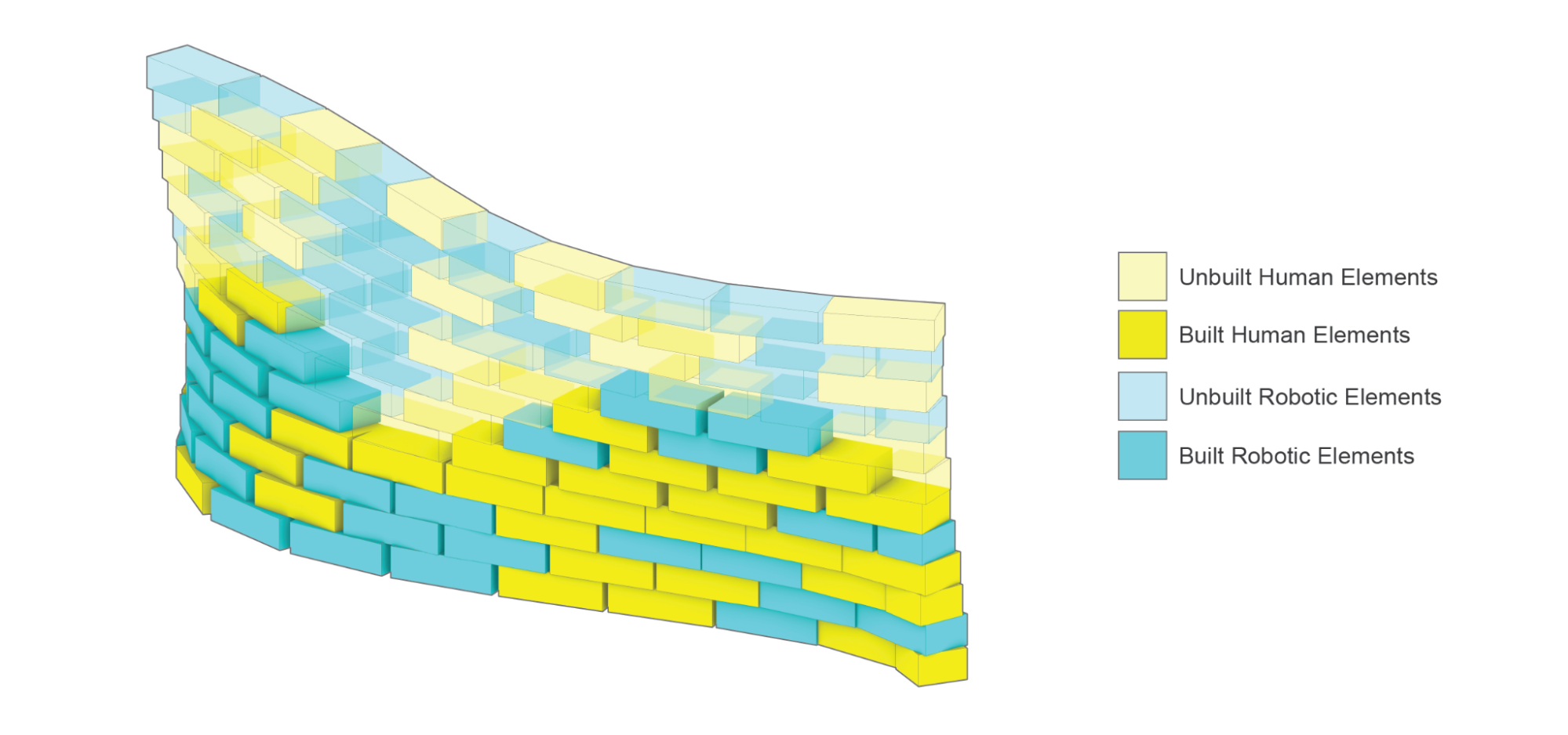
Step 4.5: Reading and Visualizing Firebase Realtime Database Information on CAD (As needed)
When needed, the Project Data can be read from the Realtime Database and visualized in Grasshopper. With a Custom-Preview Component, the output generated can be colored and displayed in Rhino. Outputs: last_built_index, step_locations, built_human, unbuilt_human, built_robot, unbuilt_robot.
last_built_index: str - The index of the last constructed element from the current active users.
step_locations: list of compas.Geometry.Frame - The location information in which the step is stored under.
built_human: list of compas.Geometry - A list of elements in the current project data that have already been built by humans.
unbuilt_human: list of compas.Geometry - A list of elements in the current project data that have not been built by humans.
built_robot: list of compas.Geometry - A list of elements in the current project data that have already been built by the robot.
unbuilt_robot: list of compas.Geometry - A list of elements in the current project data that have not been built by the robot yet.
# Import Project Manager class from compas_xr
from compas_xr.project import ProjectManager

# Define instance of Project Manager class with firebase config file path as input
pm = ProjectManager(config_filepath)

# Call Method from Project Manager Class to Return Firebase Current State
last_built_index, step_locations, built_human, unbuilt_human, built_robot, unbuilt_robot = pm.visualize_project_state(assembly, project_name)
NOTE: This component is not event based, and will need to be triggered to be updated with project information. Each time the component is triggered, it will result in the current state of the project data on the firebase.
Step 5: Define Robotic Assembly Strategy
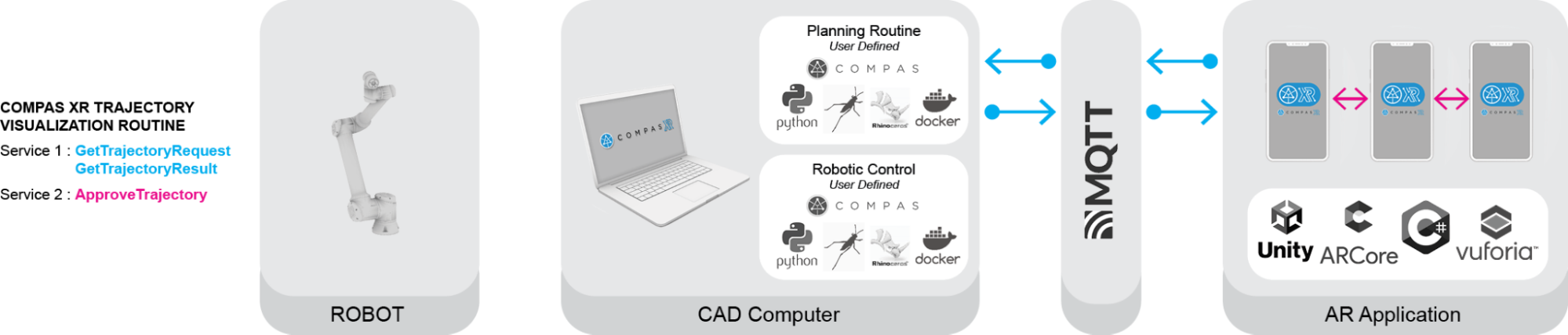
COMPAS XR facilitates human-robot collaboration by providing robust tools for reviewing, approving, and executing robotic trajectories in the Augmented Reality Space when utilized in combination with other tools provided by the COMPAS ecosystem such as COMPAS FAB. It allows multiple users to simultaneously interact with and oversee the movements of robots, ensuring precision and safety in complex operations. This collaborative environment not only streamlines the workflow but also leverages the collective expertise of various stakeholders, leading to more efficient and reliable outcomes in robotic applications.
Services Overview
COMPAS XR provides custom message classes in both the Python and C# libraries to coordinate trajectory requests and reviews across multiple users. These message classes enable seamless communication and synchronization, ensuring that all participants can efficiently collaborate on planning and approving robotic trajectories.
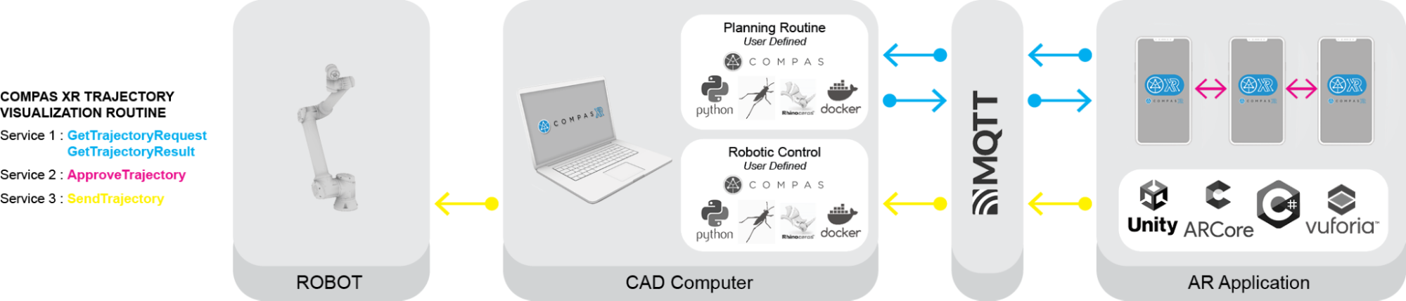
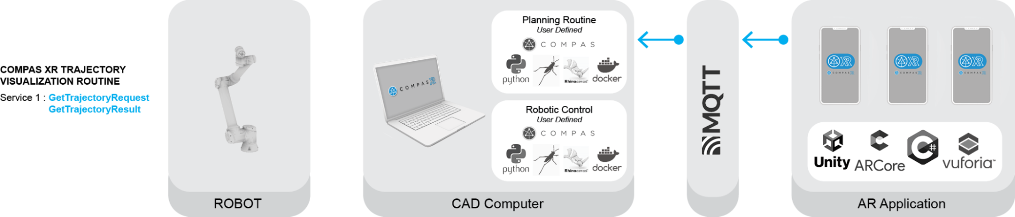
Get Trajectory Request: Message Published by each User when a trajectory for a particular building element is requested.
Get Trajectory Result: Message Published by the CAD to signify a planning result on the CAD.
Approve Trajectory: Message published by each User to signify their approval or disapproval of a provided trajectory.
Send Trajectory: Message published from the User in which requested the review. This message is used to signify approval by all users and the robotic trajectory can be sent to the Robot.
NOTE: As the messages are uniform across both the Unity C# and Python Classes. Any modifications to the structure will require modification in both compas_xr_unity and compas_xr classes.
Step 5.1: Application Request Overview:
There is a set routine that the application follows to successfully review, approve, and execute the trajectory. This routine involves several critical steps to ensure accuracy and collaboration between all Users.
Step 5.1.1: Select Robot
The application includes a drop down for simple robot selection and visualizatio, offering users the opportunity to evaluate different robots for completing the task at hand. Users can browse through various robotic options, each with detailed visual representations
// COMPAS XR Default Robot List
RobotURDFList = new List<string> {"UR3", "UR5", "UR10e", "ETHZurichRFL"};
NOTE: COMPAS XR currently defines base robot models for the robots listed above. Additionally, it is important to note that the base models will only provide the robotic elements. It will not provide custom tool attachment for each robot model.
Step 5.1.2: User Publishes Request
If the robotic element is of current priority and ready to be assembled, users will be prompted to request a trajectory upon selecting the object. Once a user requests a particular object, the application initiates a communication sequence. The user’s device publishes a GetTrajectoryRequest message to the CAD system, specifying the requested robot and the element to be assembled. This request ensures that the CAD system has all the necessary information to generate a precise and efficient trajectory for the assembly process.
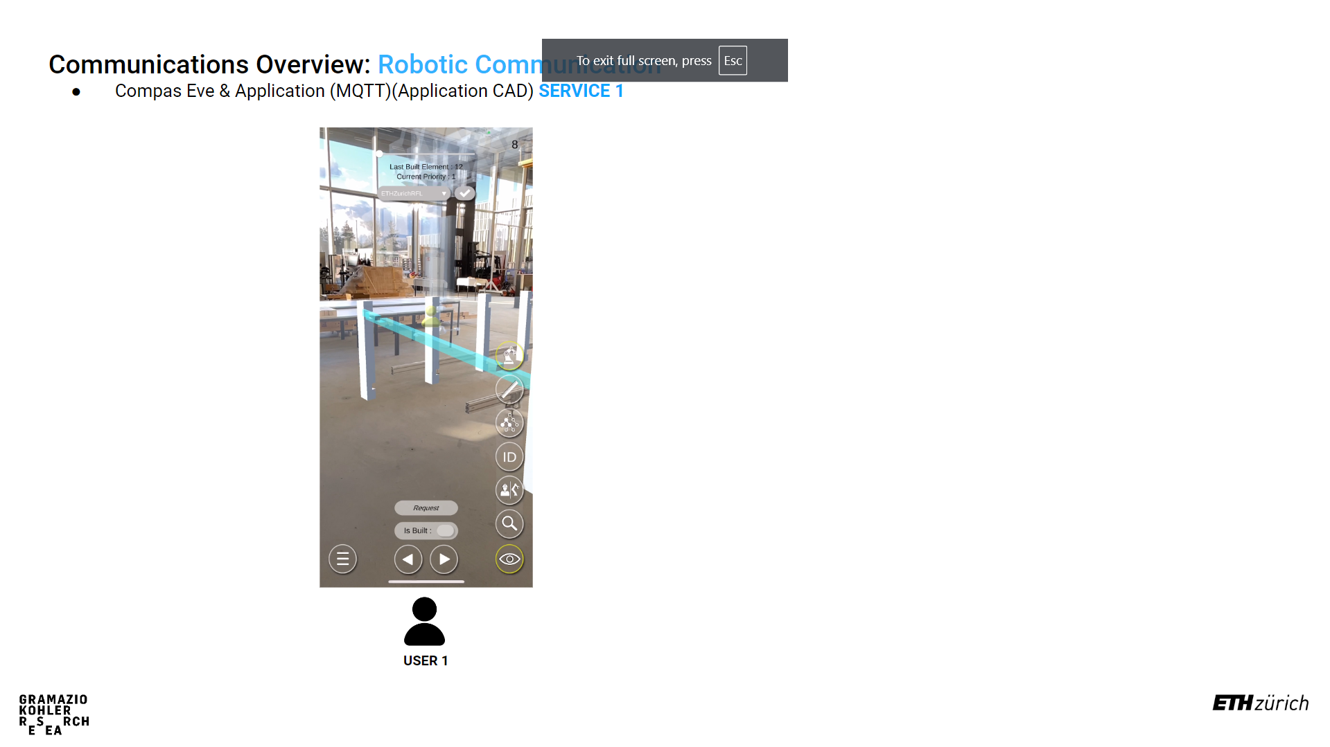
NOTE: There are a multitude of ways in which the application will prevent you from requesting a trajectory. For example, there is no active robot selected, the element is not ready to be assembled, or another active User is awaiting a trajectory for visualization.
Step 5.1.3: All Active Users Review Proposed Trajectory and Provide Individual Approval
Upon receiving the trajectory, all active users are prompted to review it and publish their approval or rejection in the form of an ApproveTrajectory message. This collaborative review process ensures that multiple perspectives are considered before proceeding with the trajectory. However, if the received trajectory is null, only the user who initially requested the trajectory will be notified and will be returned to the request service.
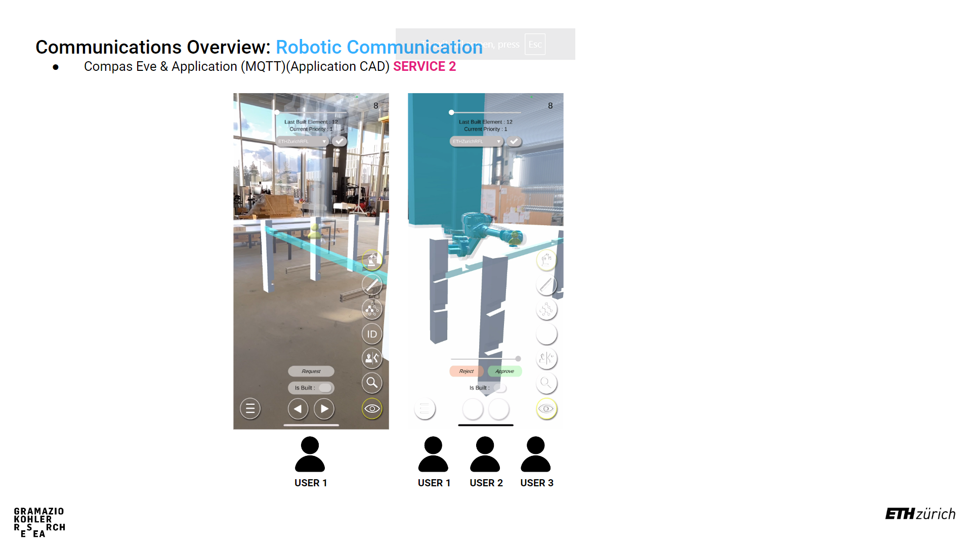
NOTE: The master approval of robotic selection is handled by the CAD. Therefore if the CAD replies with a trajectory for another robot other than the one currently selected by the User, the Users active robot will be updated. Additionally, if any user disapproves of the trajectory, all users will be immediately returned to the request service.
Step 4: Upon All Users Approval Initial Request User Publishes Execution
Upon receiving approval from all users, the initial user who requested the trajectory is prompted to proceed with the execution of the current selected element. Upon confirmation, the user’s device sends a SendTrajectory message to the CAD system. This message signifies that all users have approved the trajectory and that the movement should be executed by the Robot.
Step 5.2: CAD SetUp and Requirements:
COMPAS XR does not provide the complete planning routine; however, it offers the necessary messaging services for visualizing robotic trajectories in the Augmented Reality space. Below are the required components and steps to subscribe to and publish messages. It is important to note that additional user input is required on the CAD from each user for both planning and execution of trajectories, tailoring the process to their specific needs. For a detailed overview of possible setups, please review the example file included with the documentation. This example file will guide users through various configurations and help them optimize their workflow using COMPAS XR’s messaging capabilities.
Step 5.2.1: Select Robot
The options component is used to set up the other publisher and subscriber components. It handles the process of passing specific information to the subscribers, enabling them to publish and subscribe to the required information on specific topics. By configuring these options, users can ensure that each component communicates effectively, subscribing to relevant topics and publishing necessary data.
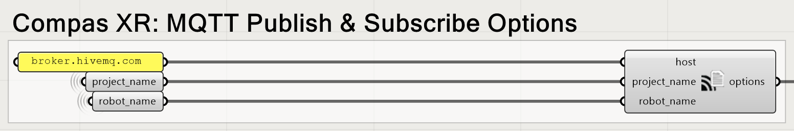
host: string - The broker intended to be used for the messaging service. - The default broker for both the Application and the CAD is HiveMQ however customization is possible depending on each users needs.
project_name: string - The name of the firebase project that is currently being worked on in the application side. - This is used to customize the topic names in both the CAD and Unity file, and is important it remain the same on in order to receive the messages.
robot_name: string - The name of the robot intended to complete the task.
# COMPAS XR Default Robot List
robot_list = ["UR3", "UR5", "UR10e", "ETHZurichRFL"]
NOTE: COMPAS XR does not include all robot models, and the currently available robot models are listed above. If an additional robot is added to the Unity file, then the robot name can be added to the list and sent with the respective messages.
Step 5.2.2: Get Trajectory Request Subscriber
The Planning Request Subscriber is used to manage GetTrajectoryRequest messages from the application to the CAD. This component updates and transmits additional information for each request, ensuring that the CAD system receives all necessary details to process and respond accurately. By handling these requests, the Planning Request Subscriber plays a crucial role in facilitating effective communication and coordination between the application and the CAD system, thereby supporting the overall planning and execution workflow.
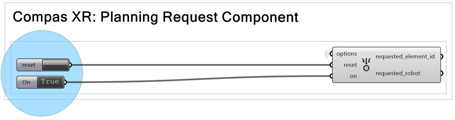
options: compasXR.options - Information passed from the COMPAS XR Options Component.
on: bool - Initializes the background work of the component.
reset: bool - Resets the individual component.
NOTE: It is very important the component be both toggled on and reset prior to receiving a request from the application. If the component is not restarted in the beginning of operation no request will be received.
Additionally the components will require specific topic creation in order to ensure that the application and CAD are only receiving messages intended. The custom topic creation example can be found below
# COMPAS XR Get Trajectory Result Topic
topic = 'compas_xr/get_trajectory_request/project_name'
Step 5.2.3: Get Trajectory Result Publisher
The Sync Result component is used to consolidate all user-defined inputs for the resulting trajectory and coordinate them into a single, unified trajectory. This ensures that all relevant information has been collected and is ready to be published to the application. By aggregating inputs from all users, the Sync Result component guarantees a comprehensive and accurate final trajectory, facilitating a cohesive and efficient execution process.
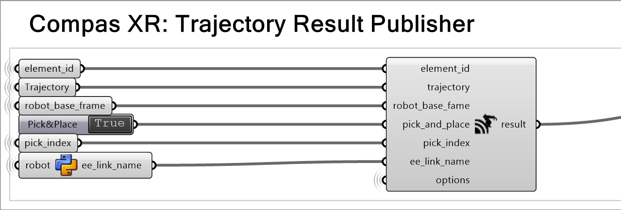
element_id: string - The number of the BuildingPlan Step that the trajectory is intended for.
trajectory: compas_fab.robots.JointTrajectory (Optional) - The trajectory that is intended to be published. - A null trajectory will result in notification of the user that requested the trajectory, but not an error.
robot_base_fame: compas_fab.robots.JointTrajectory - The location of the robot in relation to the design object.
pick_and_place: bool - Notifies the application if the trajectory is intended to attach a building element in the process. - Default value is False
pick_index: int (Optional) - The index (configuration) in the trajectory in with the element should be attached to the robot.
ee_link_name: string (Optional) - The link name in which the element should be attached to.
options: compasXR.options - Information passed from the COMPAS XR Options Component.
The Planning Result Publish component is responsible for publishing the planning result from the CAD to all active users through a GetTrajectoryResult message. This component ensures that the finalized trajectory, after being processed and coordinated, is made available to the application.
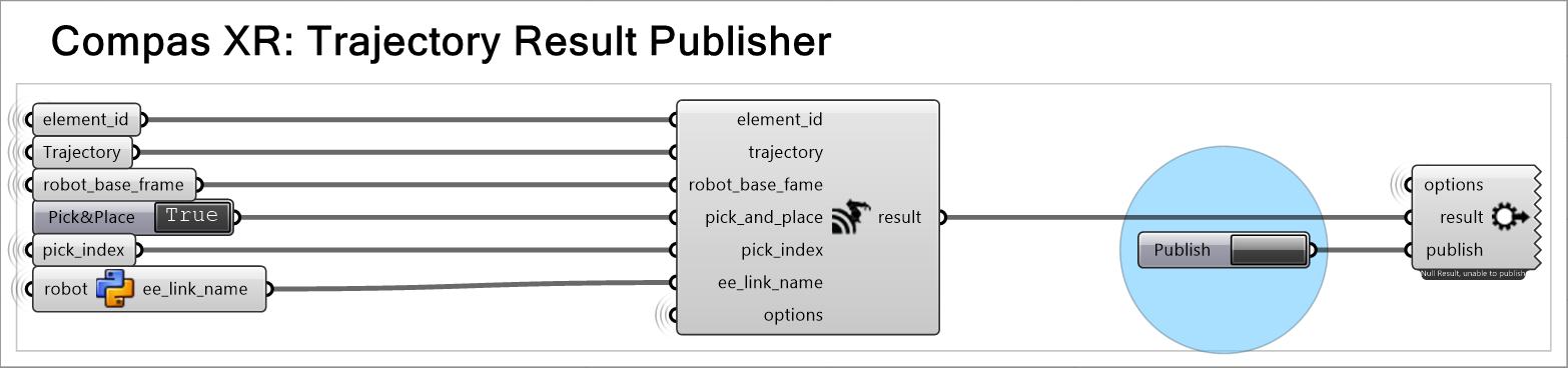
options: compasXR.ghpython.options - Information passed from the COMPAS XR Options Component.
result: compasXR.ghpython.TrajectoryManager - Information passed from the Sync Result component.
publish: bool - User input used to publish the message.
Additionally the components will require specific topic creation in order to ensure that the application and CAD are only receiving messages intended. The custom topic creation example can be found below
# COMPAS XR Get Trajectory Result Topic
topic = 'compas_xr/get_trajectory_result/project_name'
Step 5.2.4: Send Trajectory Subscriber
The Execution Service component is a custom subscriber for SendTrajectory Message sent from the Application to the CAD, and is used to send the approved trajectory from the application to the robot for execution. Upon receiving user approval, this component transmits the trajectory details, ensuring the robot receives the precise instructions needed for execution.
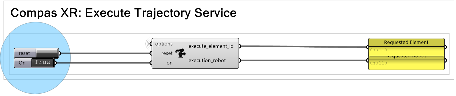
options: compasXR.options - Information passed from the COMPAS XR Options Component.
on: bool - Initializes the background work of the component.
reset: bool - Resets the individual component.
NOTE: It is very important the component be both toggled on and reset prior to receiving a request from the application. If the component is not restarted in the beginning of operation no request will be received.
Additionally the components will require specific topic creation in order to ensure that the application and CAD are only receiving messages intended. The custom topic creation example can be found below
# COMPAS XR Send Trajectory Topic
topic = 'compas_xr/send_trajectory/project_name'
Step 5.3: Adding a Custom Robot to the Application
Although the application includes many robots that can be used for review and execution, most digital fabrication and production tasks require custom robotic setups and additional customized end effectors. The current version of the application does not support the runtime processing of custom robots or end effectors. Below are the steps to customize and import your robot into the application for visualization in AR through COMPAS XR.
Step 5.3.1: Reading Robot Description and Unity Game Object Creation.
Start docker desktop (it doesn’t have to stay open, but we just need to make sure it is running in the background at least).
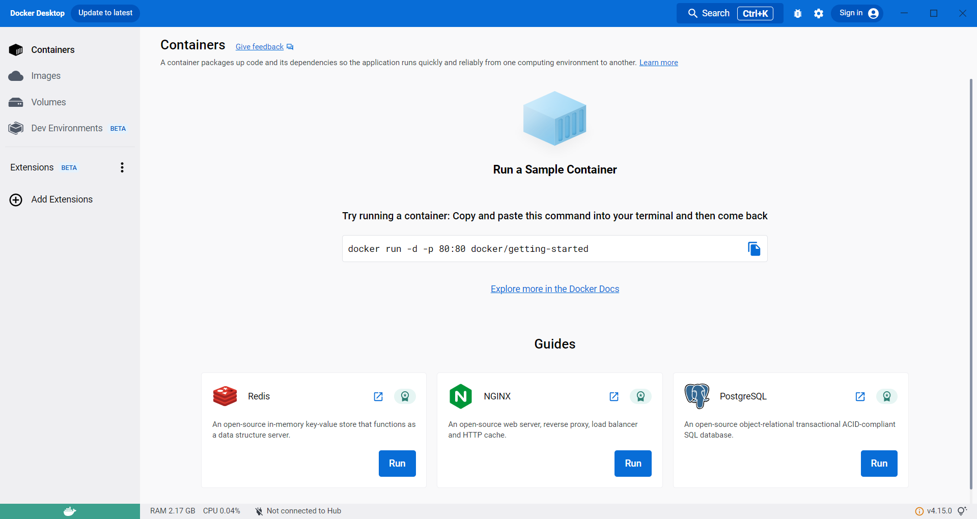
Navigate to the docker compose.yml in VS Code and compose up.
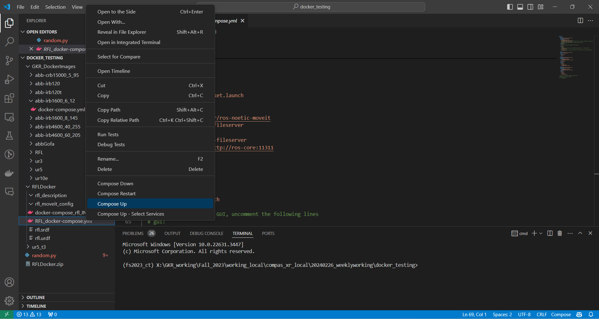
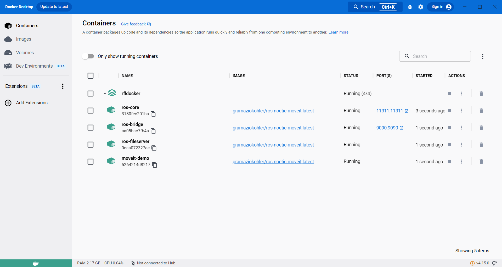
Then in docker desktop you should see the containers running.
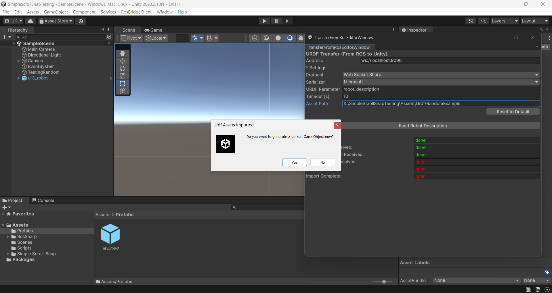
Then in Unity go to RosBridgeClient –> Transfer URDF from ROS.
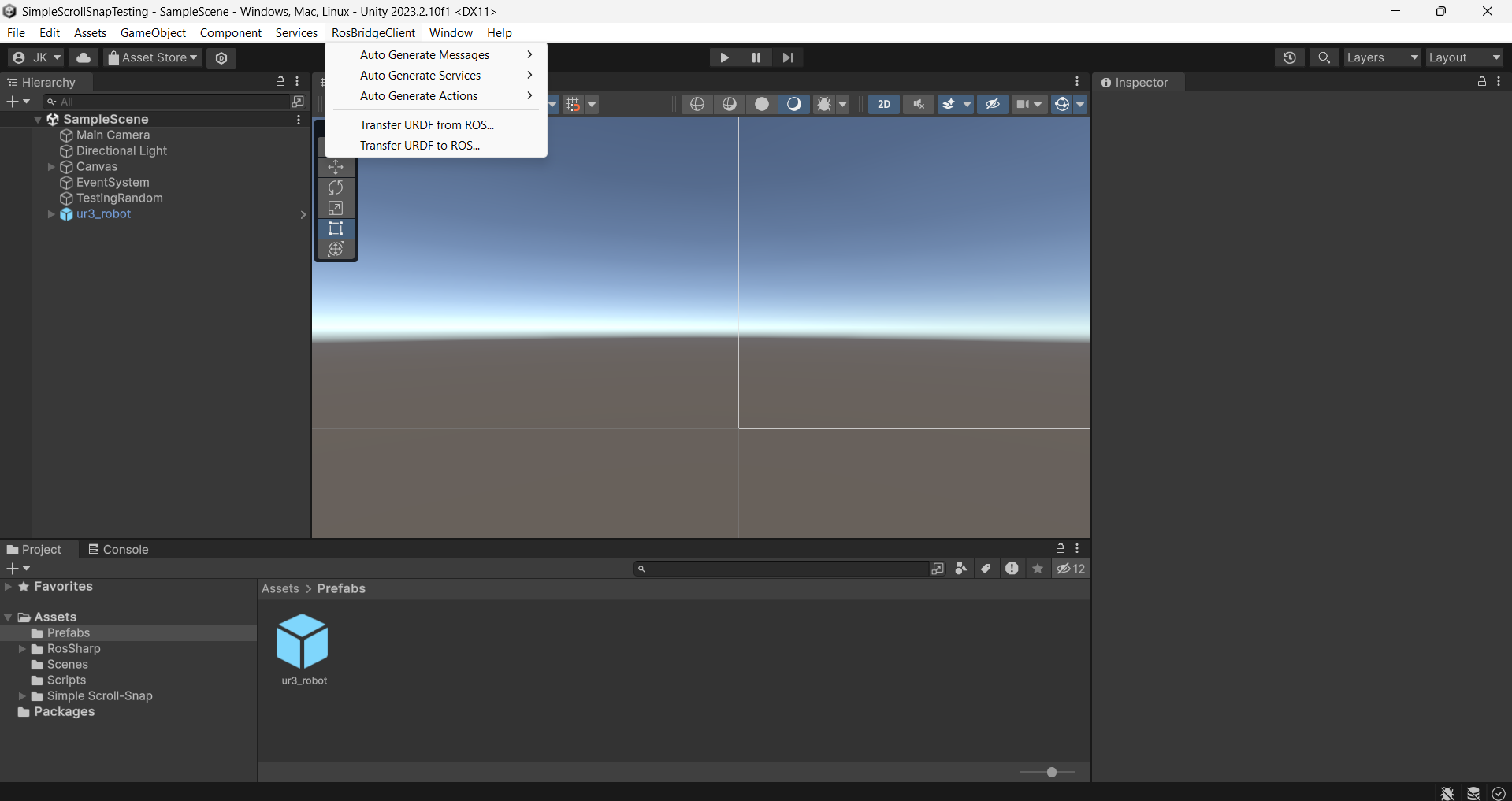
This should bring up another window TransferFromRosEditorWindow.
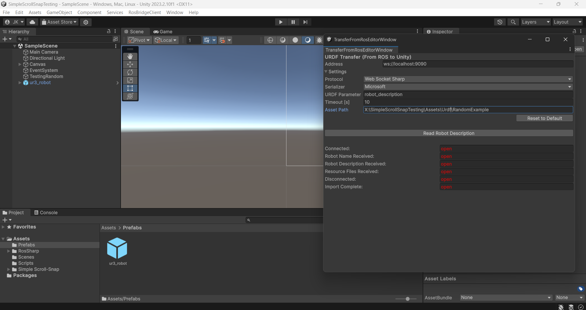
It is very important to check the settings… and are listed below:
# Unity URDF GameObject Import Settings

Address: ws://localhost:9090 (Basically just telling it to read the container that is running on my computer.
Protocol: Web Socket Sharp
Serilizer: Microsoft
URDF Paramater: robot_description
Timeout [s]: 10
(THE MOST IMIPORTANT ONE) Asset Path: Should be defined to the Assets folder of your unity project ex. ...\Assets\Urdf\MyCustomURDFName
Press the Read Robot Description button.
This should prompt a window that says “Do you want to generate a default GameObject now?”
9. Then it should make a game object from the URDF, in which Config Values can be assigned and can be used as in the native Unity GameObject methods.
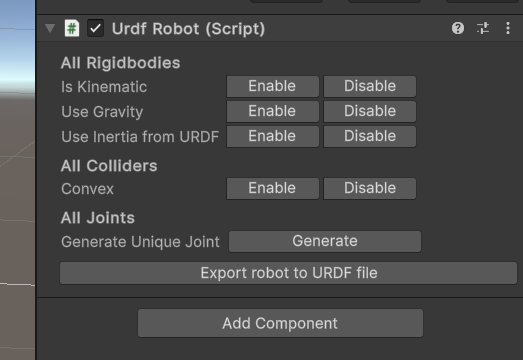
Step 5.3.2: Set Up of Robot Prefab in COMPAS XR Unity.
1. Select your robot to inspect the structure of the URDF. It is important to confirm that the Use Gravity setting is Disabled and the Is Kinematic setting is Enabled.
2. Place your GameObject in the MainGame scene. Additionally ensure that the robot is under the parent PrefabObjects and its child game object RobotPrefab.
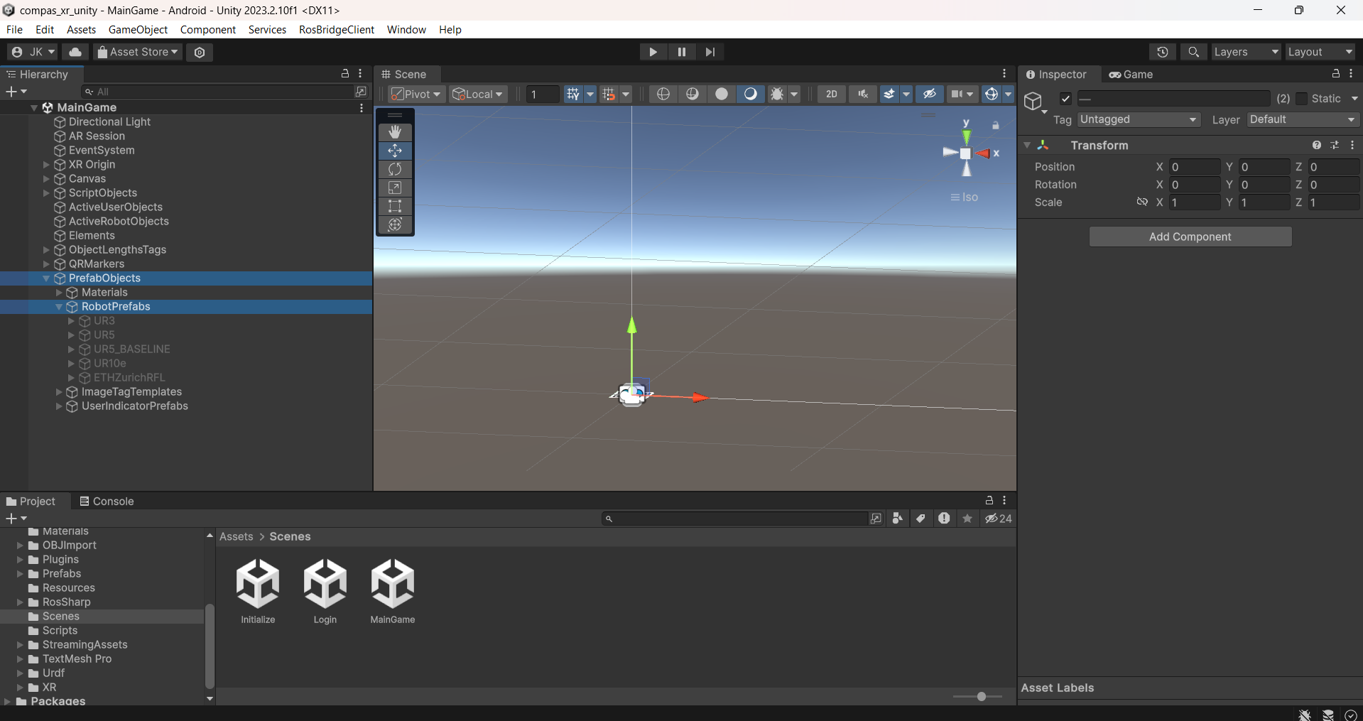
3. Navigate to the TrajectoryVisualzier.cs file located in Assets/Scripts/TrajectoryVisualizer.cs of the COMPAS XR Unity file, and input your robot name into the RobotURDFList.
// COMPAS XR Default Robot List
RobotURDFList = new List<string> {"UR3", "UR5", "UR10e", "ETHZurichRFL", "MyCustomURDF"};
4. The URDF should be added to the Default Robots list and available for use in the application at runtime upon next build.
NOTE: The read and use of URDF game objects in unity can be very unpredictable, and often produce unfavorable results as it is fully dependent on the structure of the URDF. It is very important to take note of any errors that arise throughout the import process. Additionally adding custom robots will require testing to ensure that everything is working properly.
Step 6: Release Procedures
Once you have cloned the repo compas_xr_unity and made all desired code changes or refinements, you are ready to release the application to a device. The following procedures explain the release process for both iOS and Android devices, as well as provide installation instructions for each operating system.
Release Procedures for Android Devices
Android devices utilize .apk files that are directly installable to the device. This section of the documentation explains the process of creating an .apk file from Unity and provides instructions on how to install the .apk file directly onto an Android device.
Step 6.1: How to Build for Android Devices from Unity
Step 6.1.1: Update Project Settings
Select the File > Build Settings menu option.
Select Android in the Platform list and click Switch Platform to set the target platform.
Wait for the spinner (compiling) icon to stop in the bottom right corner of the Unity status bar.
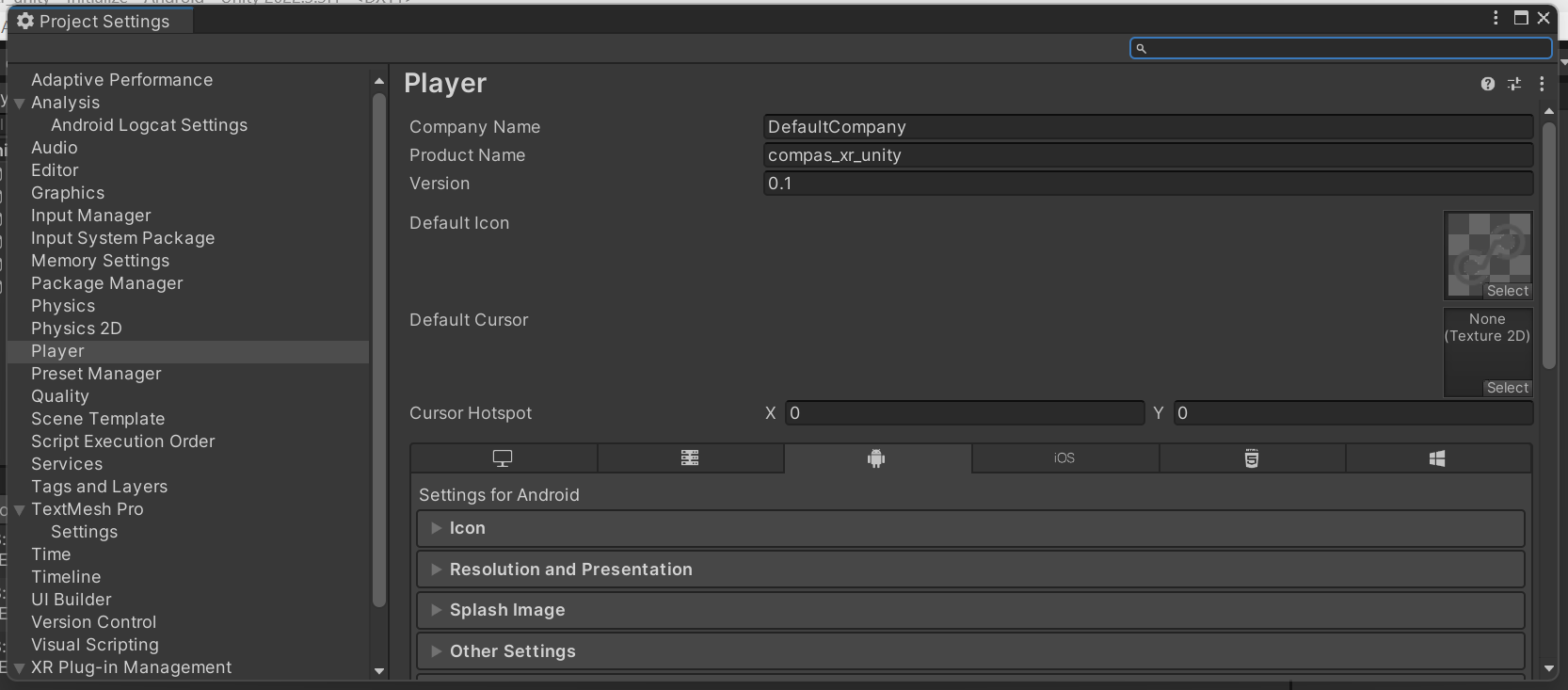
Select the active platform and click Player Settings.
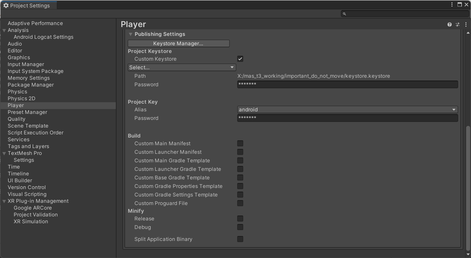
Step 6.1.2: Generate SHA key for App Signature
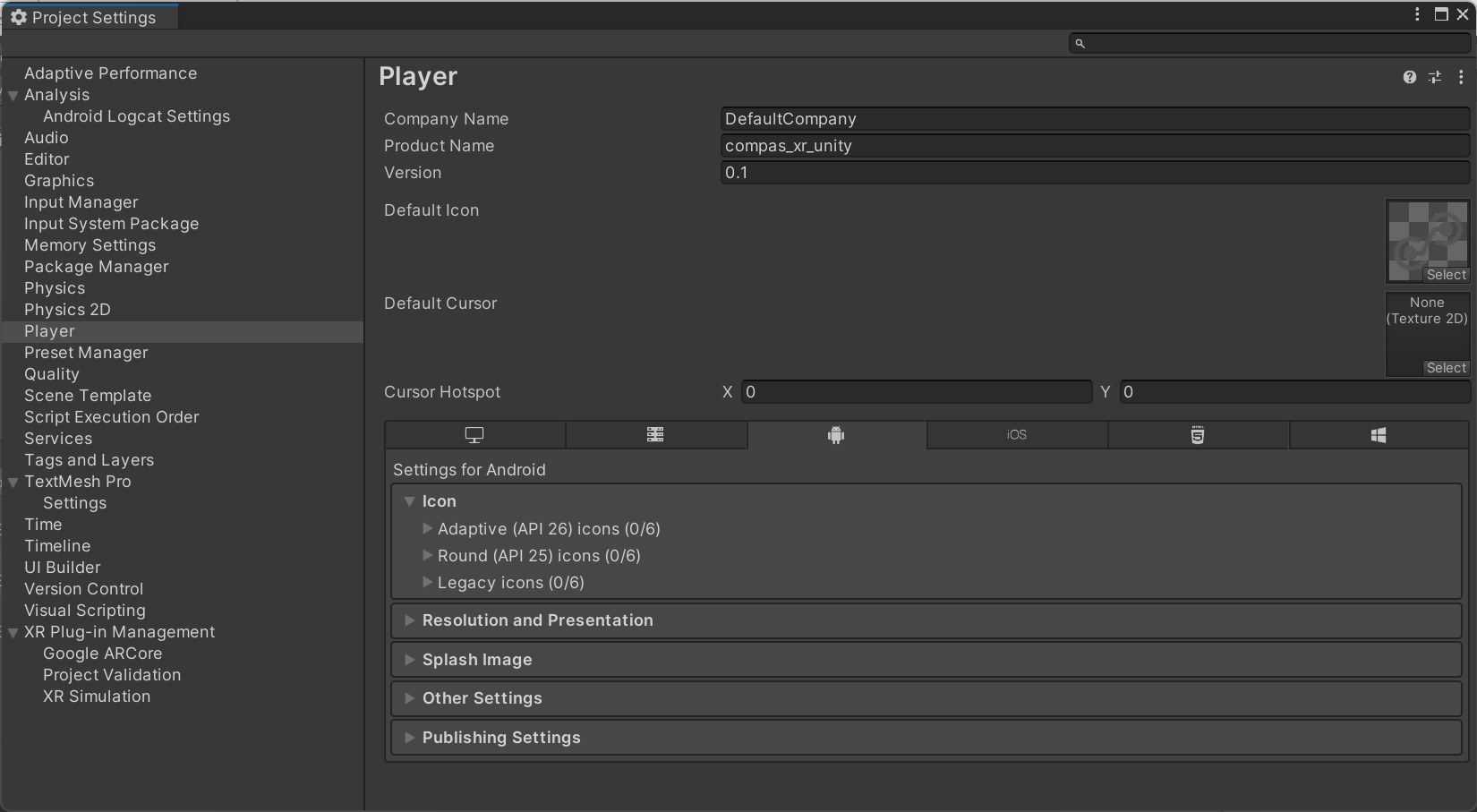
Step 6.1.3: Update Additional Player Settings
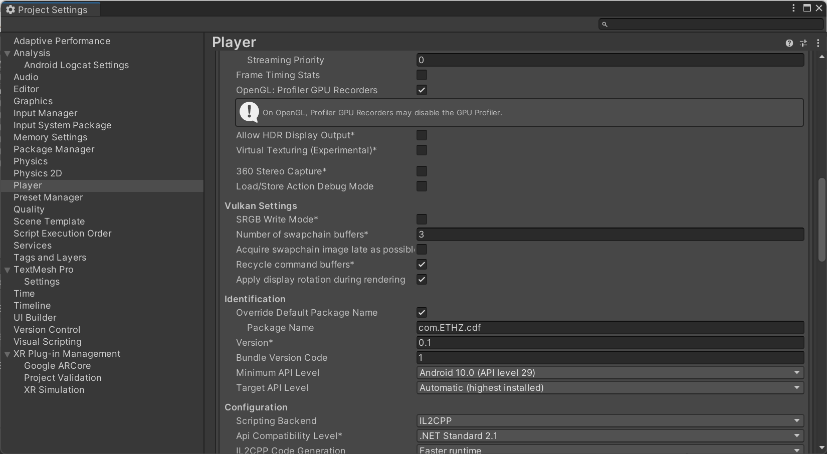
1. In Player Settings, under the Android panel: scroll down to Identification / Override Default Package Name/ and update Package Name to the value of the Bundle Identifier you provided when you registered your app with Firebase as shown in the Create Apps on Firebase.
2. In File > Build Settings, click Build and Run to build the project on an Android device. * In case the device is not a developer device, scroll at the bottom to the Turning Devices into Developer Devices section. Alternatively, one can just Build to obtain the apk and distribute it to Android devices.
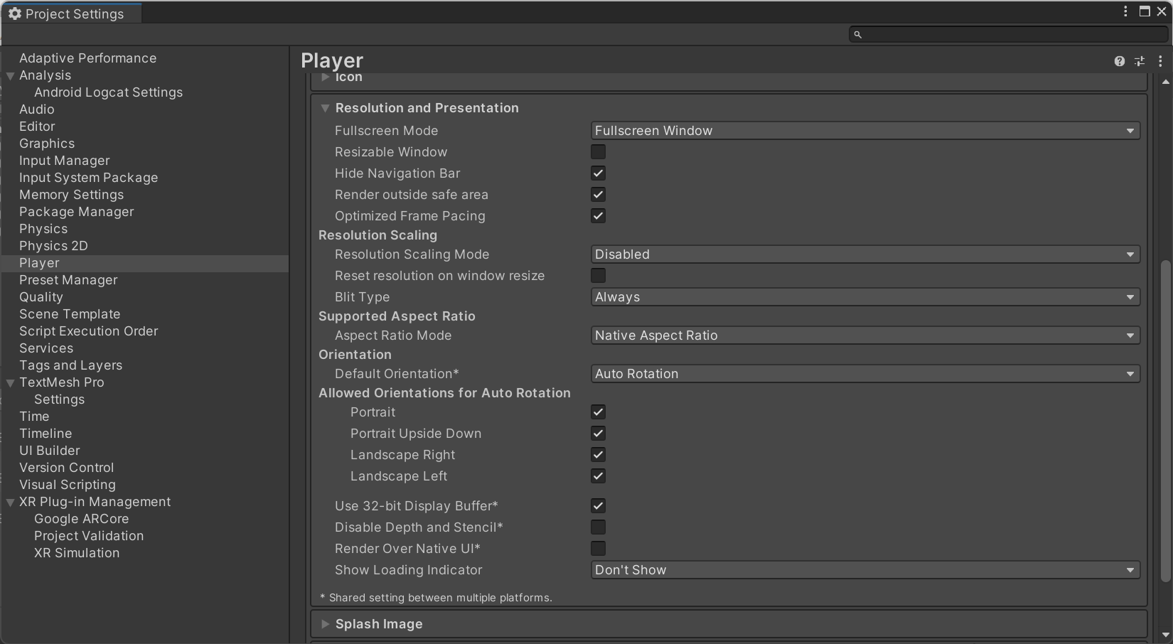
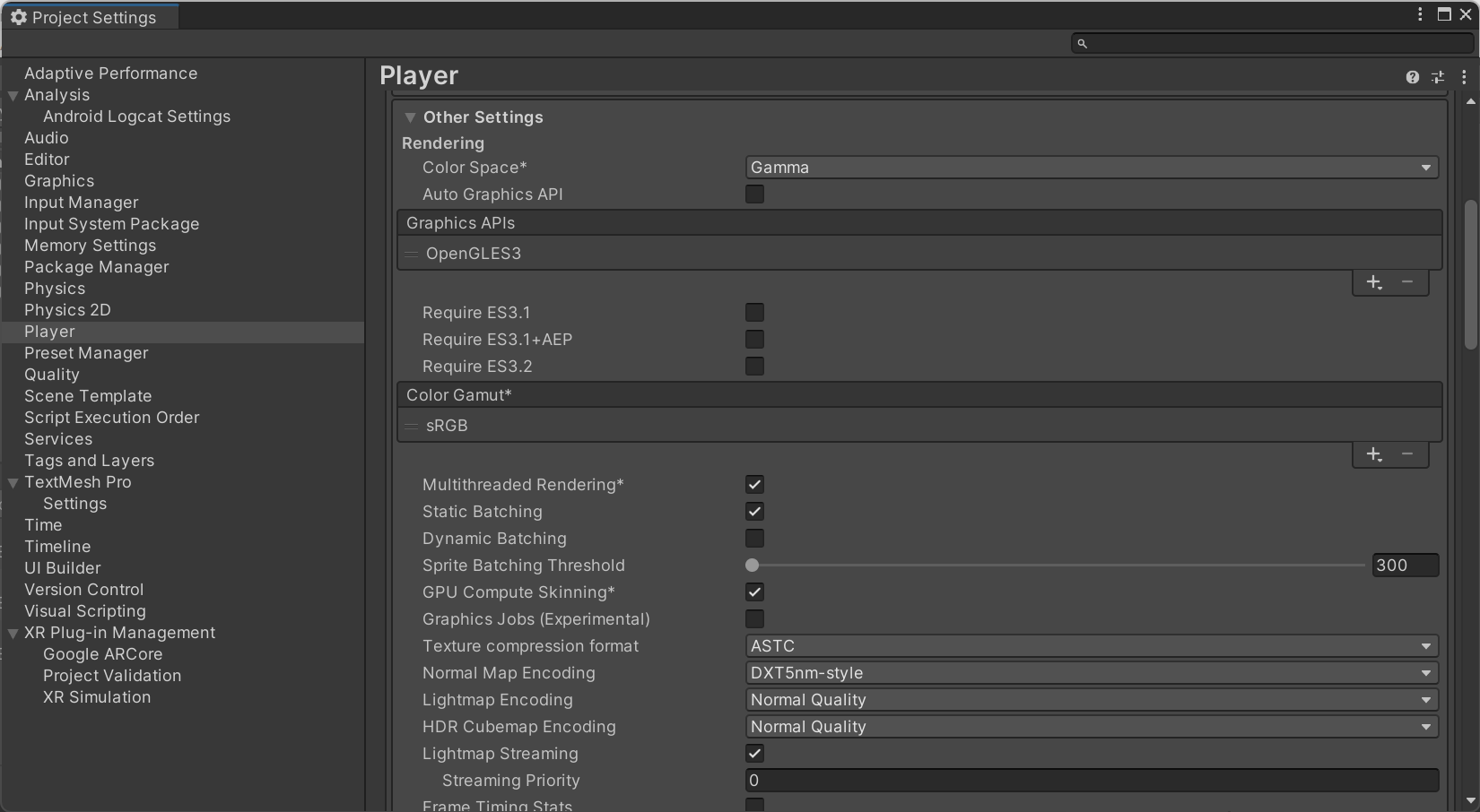
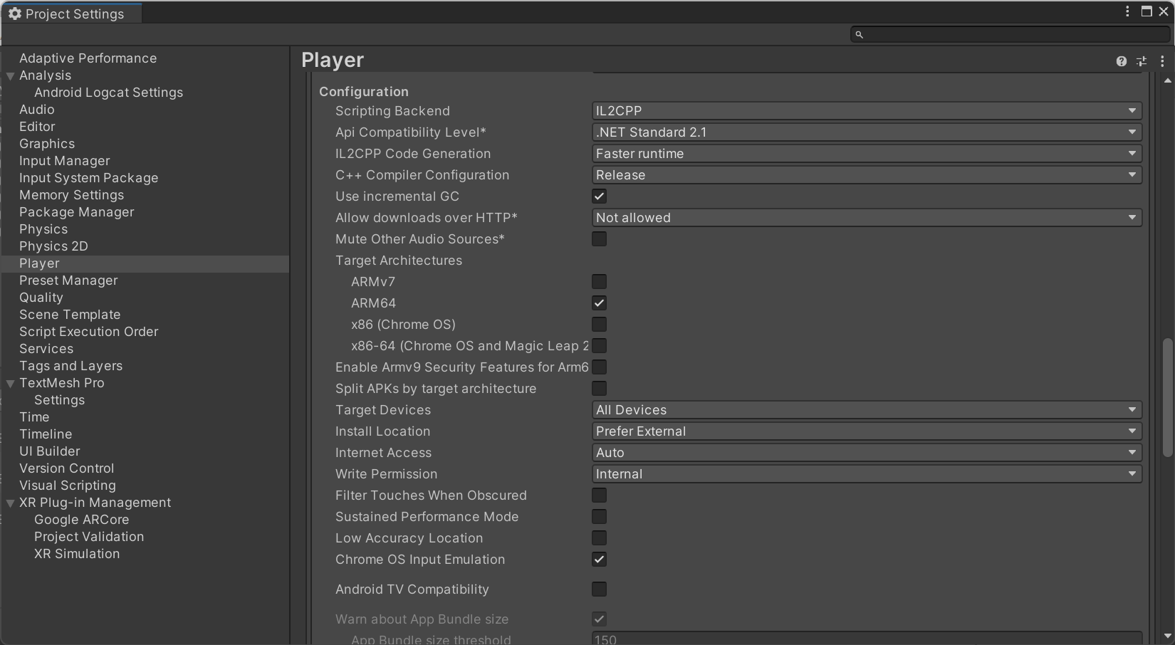
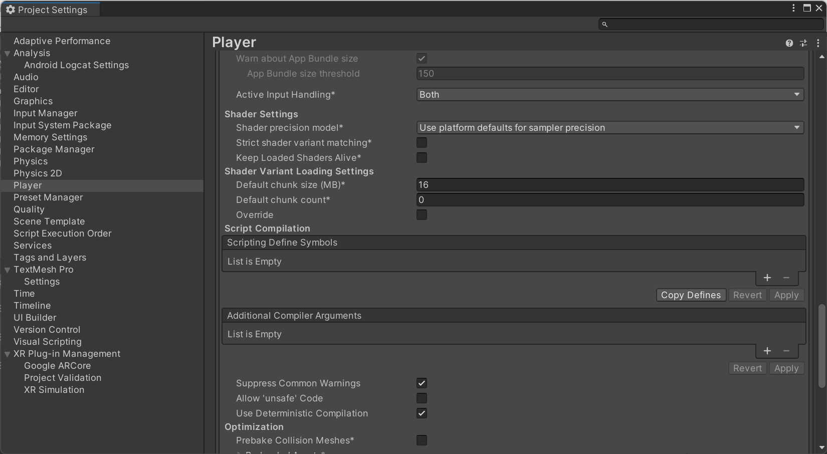
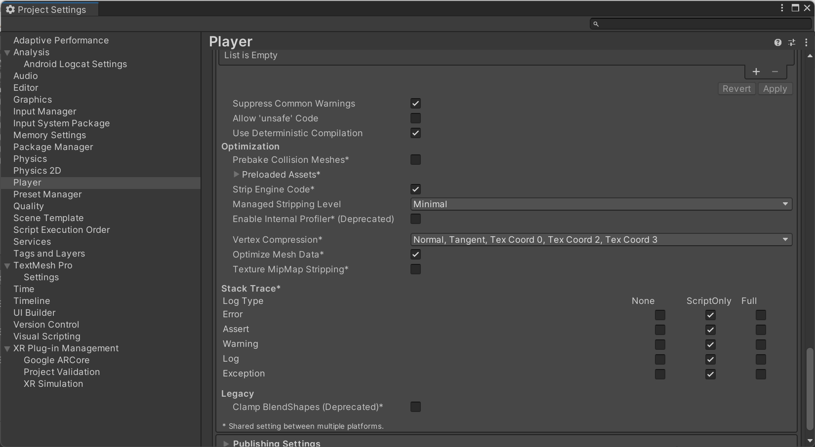
NOTE: If errors occur in the build process of the Android Device please review all additional Player Setting (shown below) to ensure that your player settings match the existing compas_xr_unity build settings.
STep 6.2: How to Install APK Files on your Android Device
Step 6.3 How to turn an Android Device into a Developer Device
In order to install and test apps that are not available on the Google Play Store to an Android Device you first need to enable Developer Mode. Enabling Developer Mode allows you to use essential developer tools and options, such as USB debugging. This is crucial for deploying and testing custom .apk files directly from your development environment, like Unity.
Go to “Settings”.
Tap “About device” or “About phone”.
Tap “Software information”
Tap “Build number” seven times.
Enter your pattern, PIN or password to enable the Developer options menu.
Release Procedures for iOS Devices.
This guide outlines the process for building and installing an iOS app from Unity using Xcode, detailing steps to handle dependencies and configurations. It includes instructions for setting up your Unity project for iOS, resolving CocoaPods issues, configuring Xcode, and enabling developer mode on your iOS device.
Step 6.4: How to Build for iOS from Unity
Step 6.4.1: Building and Installing iOS App in Unity and Xcode
Select the File > Build Settings menu option.
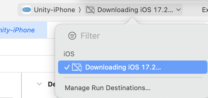
Select iOS in the Platform list and click Switch Platform to set the target platform.
Wait for the spinner (compiling) icon to stop in the bottom right corner of the Unity status bar.
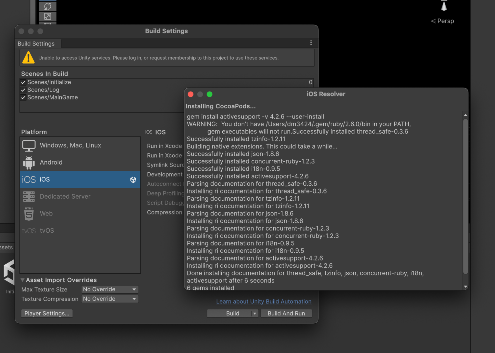
Once the target platform has been switched to iOS, Unity will try to install CocoaPods, an iOS resolver.
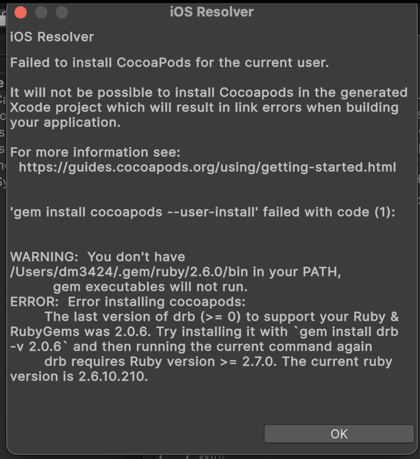
Most likely it will fail and you will need to do the following fixes:
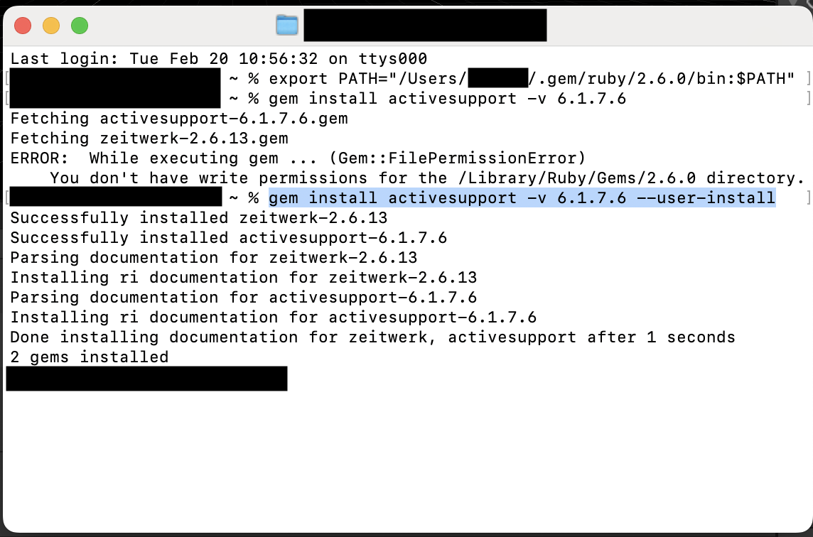
Solution A: in Terminal
Set the export path for gems as follows:
export PATH="/Users/username/.gem/ruby/2.6.0/bin:$PATH"
Install gem active support: gem install activesupport -v 6.1.7.6 --user-install
Install gem active support:
gem install activesupport -v 6.1.7.6 --user-install
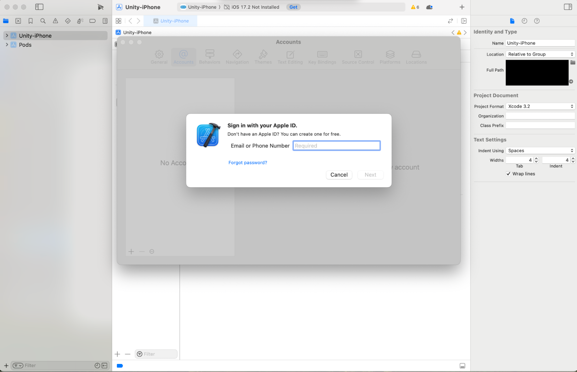
Solution B: in Xcode
Make sure you have Xcode and the Developer Tools installed on your MacBook. If you don’t, go to your MacBook’s AppStore and install Xcode.
Sign in with your Apple ID.
Solution C: back in Unity
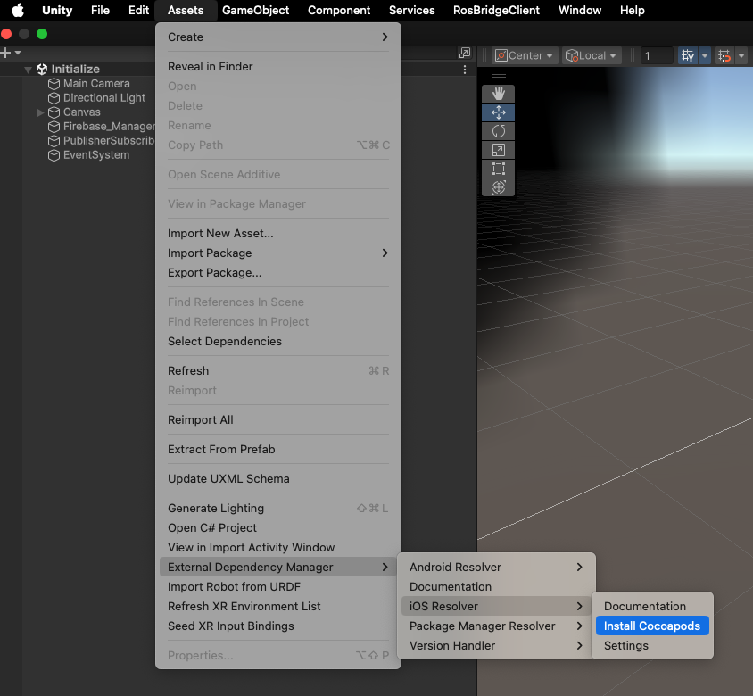
Under Assets > External Dependency Manager > iOS resolver > Install CocoaPods
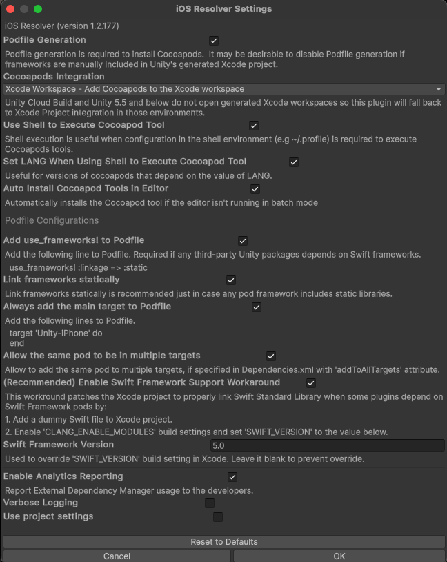
Under Assets > External Dependency Manager > iOS resolver > Settings check that you have matching settings with the ones below:
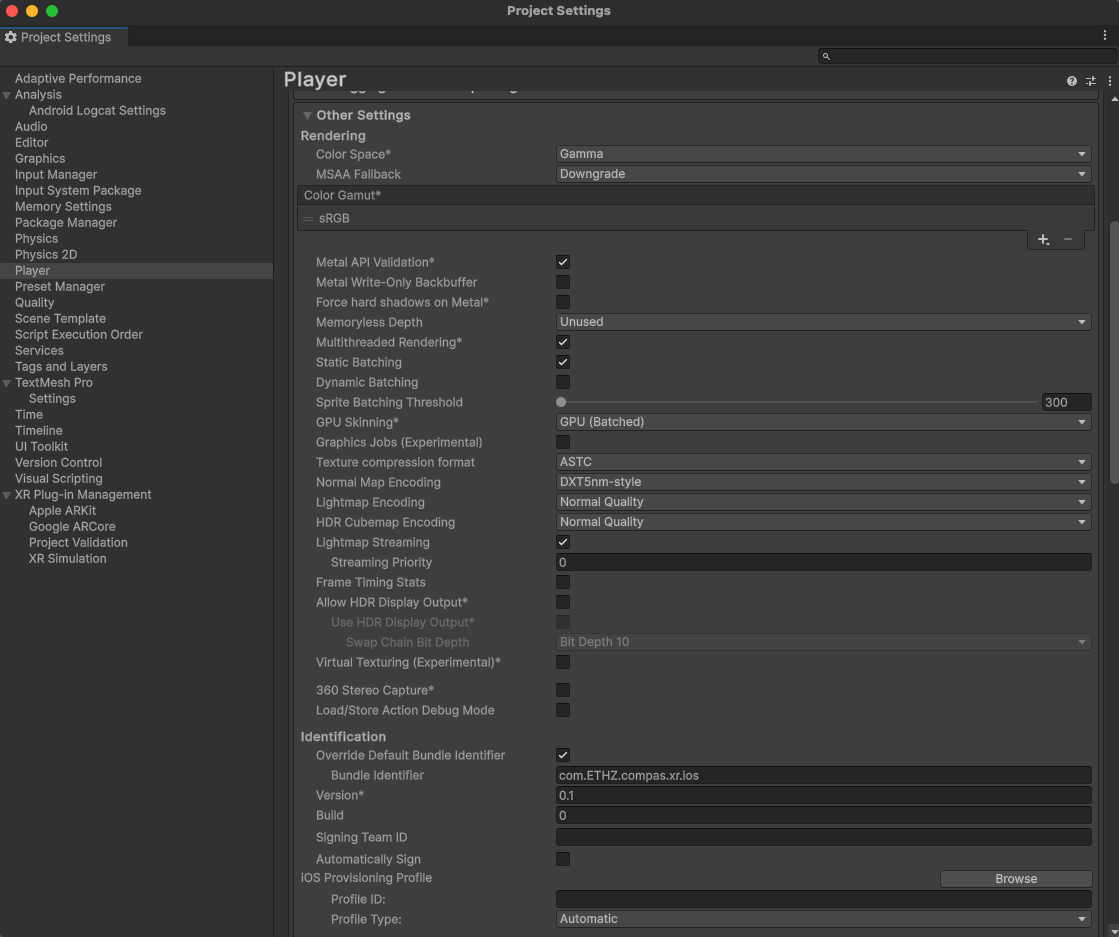
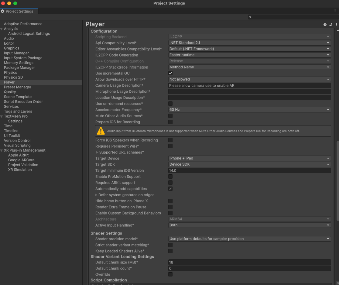
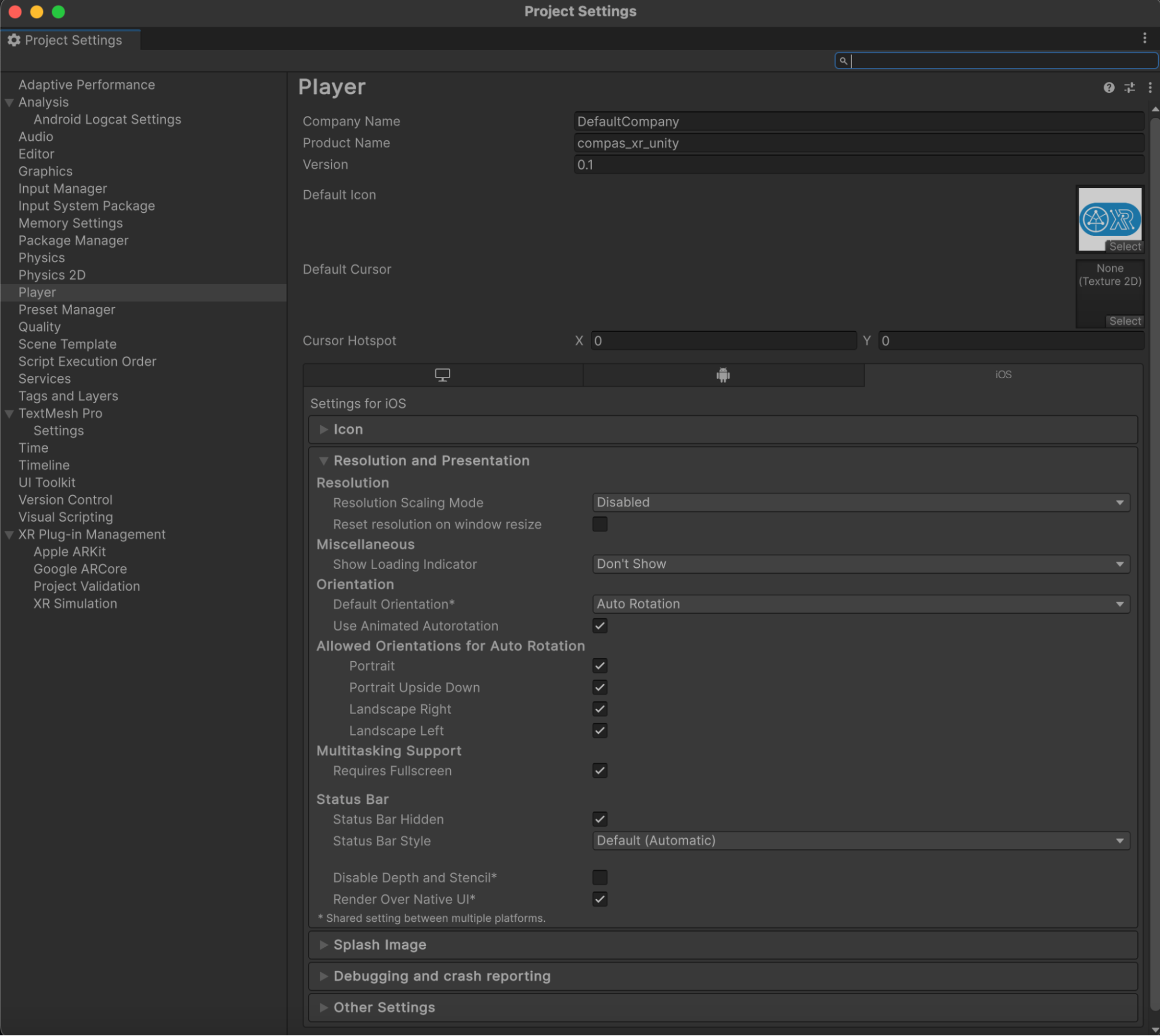
Select the File > Build Settings, Player Settings, and select the iOS panel
Scroll down to Identification / Override Default Package Name/ and update Package Name to the value of the Bundle Identifier you provided when you registered your app with Firebase.
Scroll down to Camera Usage Description and write a message describing the need to use the camera, such as “please allow camera use for AR”.
Scroll down to iOS version and pick the adequate version (min. 14 to support current project packages).
In Resolution and Presentation select Render Over Native UI
NOTE: If an error occurs, during a build, check player settings against default player settings depicted below:
NOTE: Ideally one would Build or Build and Run the project from a MacBook that has Xcode installed.
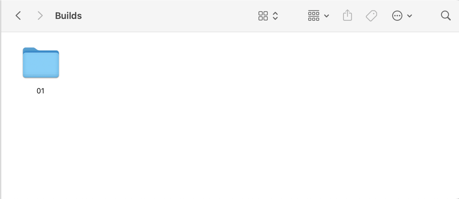
In File > Build Settings click on Build and select a folder location on your drive for the build. Ideally you should create a folder called Builds and within it you can create individual files for each build.
Step 6.4.2: How to Install on iOS from Xcode:
NOTE: Your iOS device will need to be turned into a developer device before the first installation
In Finder:
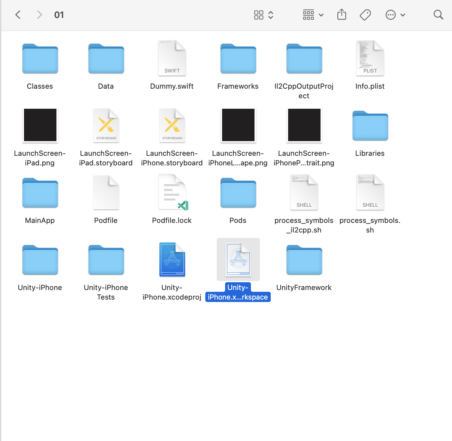
Open the Builds folder and find the file with the last build on your computer, eg. 01
Select the BuildName”.xcworkspace file and open it with Xcode. Make sure you open the .xcworkspaceand not the.xcodeproj
In Xcode:
In Xcode click the file’s name on the left column to open the Settings
Under Signing and Capabilities > All, tick Automatically manage signing and confirm Enable Automatic
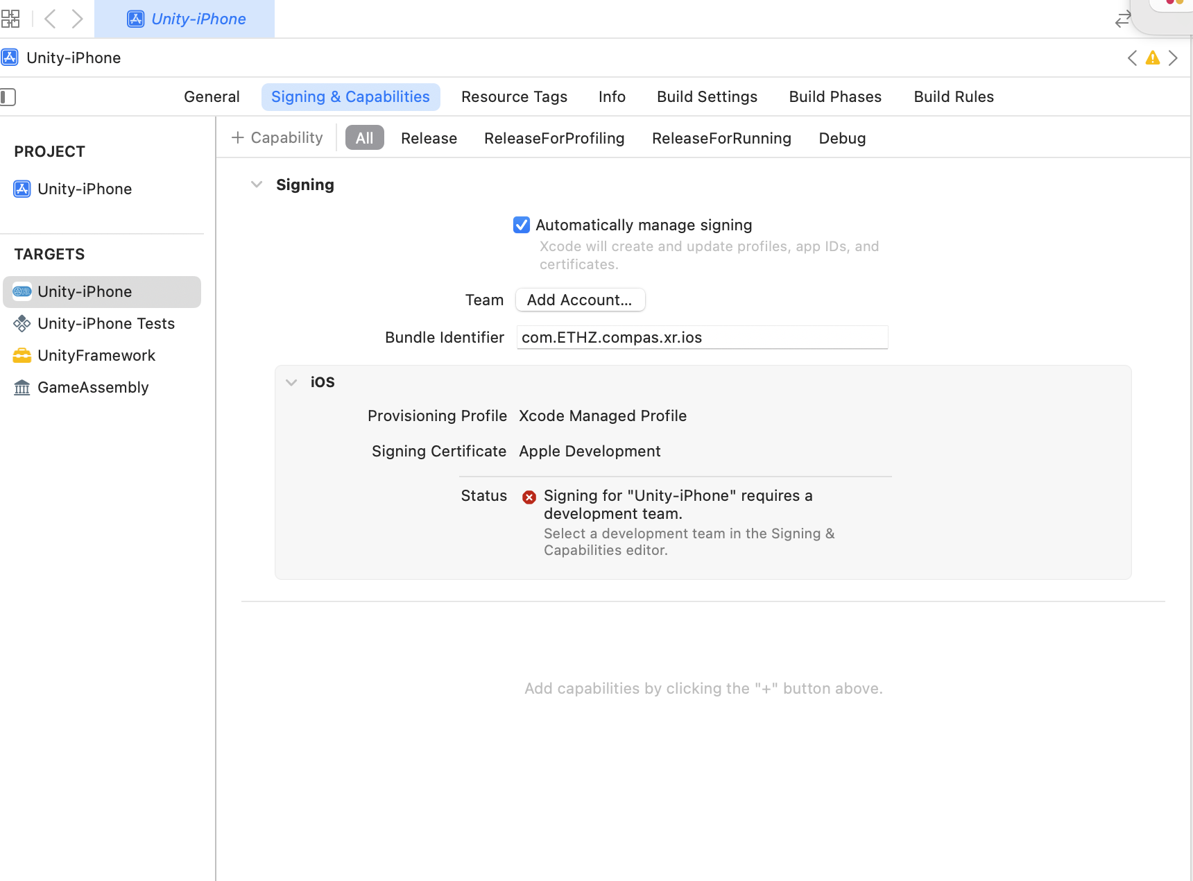
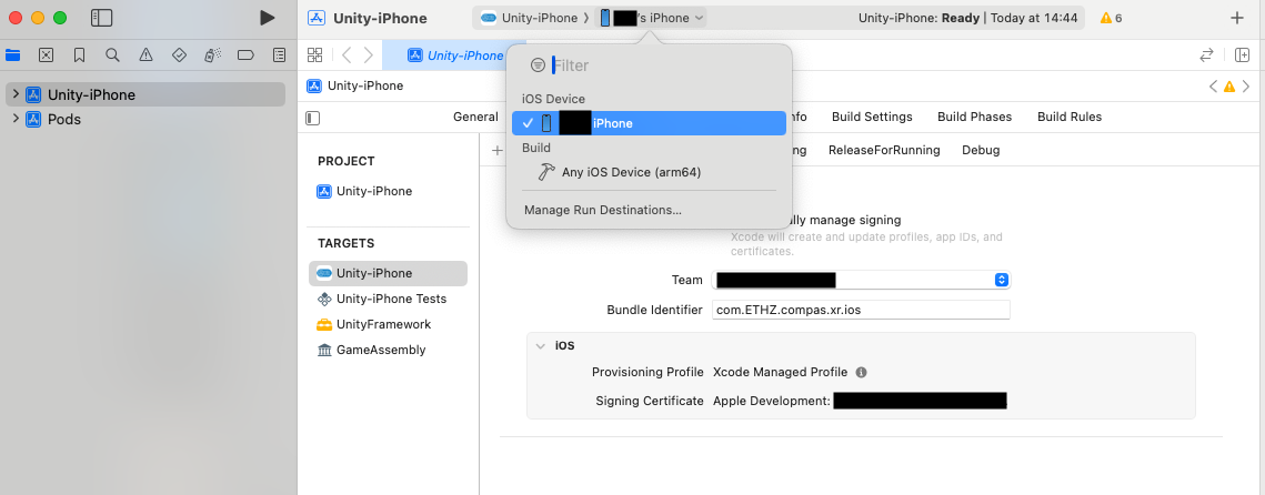
Under Team, open the drop-down down and select the development team/individual.
Optional: this is the last chance to adjust the Bundle Identifier and App Name before installing.
At the top, make sure the iOS device is connected and click the play triangle to start building and installing on the device.
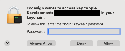
The first time you build with Xcode, it will ask for the MacBook’s password for codesign. Click on Always Allow as many times as the pop up appears.
You will be asked to unlock the device and the app will install and open automatically.
How to turn an iOS device to developer:
Connect your device to your MacBook via a USB cable.
Open Xcode.
On your device, go to the Settings app, and navigate to Privacy & Security > Developer Mode.
Enable the toggle.
You will receive a prompt from iOS to insert your passcode and restart your device.
Press Restart.
Once again, go to the Settings app, and navigate to Privacy & Security > Developer Mode and check that the toggle is on.
Link for Installable Xcode Build:
Download the Build folder from this link, unzip and install as described above.
Step 7: User Interaction
Game Scene Progression
The application progresses through several key scenes: Firebase Initialization, User Login, and Main Game. It begins with Firebase Initialization, this scene is used to start an instance of the application, and connect to the specified user inputs information. Next, the User Login scene is used to record each individual user’s login, device, date, and time. Once logged in, users are directed to the Main Game scene, where they can engage with the core content, personalized with their data from Firebase.
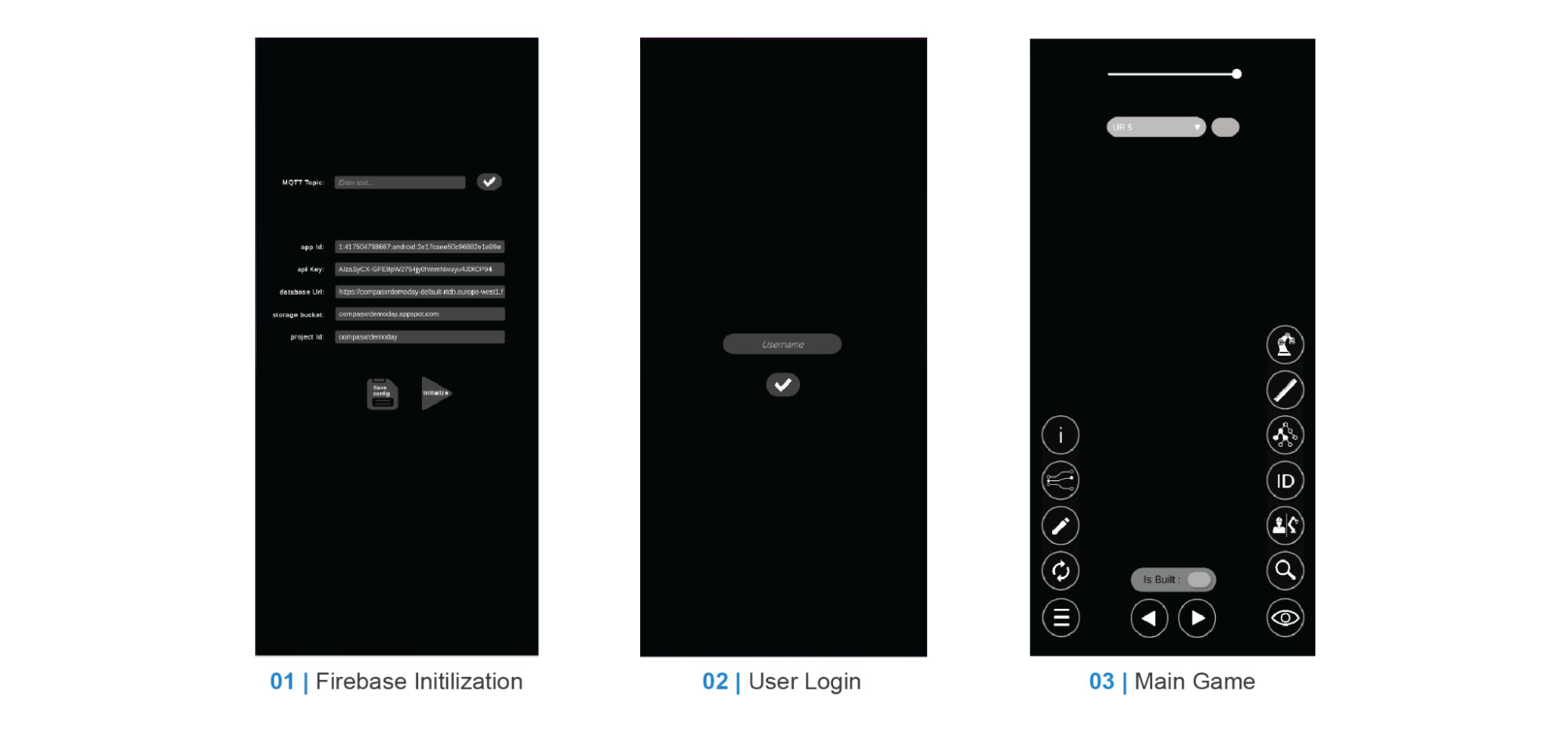
Step 7.1: Firebase Initilization
This scene is used to establish the users connection to a particular firebase. This scene includes many required user inputs, and options to save, and send input values for establishing the connection.
User Inputs
Optional:
MQTT Topic: If you wish to send the firebase information from grasshopper you will need to input the particular topic name in which you would like to subscribe, and start the subscription.
Required:
app Id: The app uses its unique Firebase app ID to connect to backend services.
api key: A Unique identifier for Firebase project requests.
database url: The end point for Firebase Realtime Database access.
storage bucket: The end point for Firebase Cloud storage file uploads & Downloads.
project Id: The end point for Firebase Cloud storage file uploads & Downloads.
User Options
Save config: This button will allow the user to save the current inputs of user input fields. This allows the user to only input these values once, and can be used upon restart of the application. Additionally, this is device specific and if you wish to connect to a new firebase these values must be overwritten.
Initialize: The initialization button is used to initialize the connection to firebase with the selected values, and progress to the next scene.
NOTE: It is important that each user input values from their specific firebase accurately, or it can result in a failure to connect or visualization of incorrect information. These connection settings can be found in the same location as noted in the Connect Grasshopper to Firebase section. However Additionally the App ID can be found by selecting the particular app created in the Create Apps on Firebase portion of the documentation.
Step 7.2: User Login
This scene is used to establish a user and device record with particular user names. Additionally, it will record each user’s login to the firebase in the Firebase Realtime Database.
User Inputs
Required:
Username: This is the username that you wish to record with your firebase entry. By inputting the same username with each instance of the application, each user will record their devices and time records.
User Options
Initialize: The initialization button is used to write user values to the firebase directly, and additionally advance to the main game.
NOTE: If the application freezes at this point, it is most likely that one of the values from the firebase configuration is incorrectly set and that the application was unable to initialize the correct application. If this is the case please return to the Initialization Scene and review User Input firebase configuration values.
Step 7.3: Main Game
This scene is where the core functionalities are, and will be explained in further detail in the Main Game User Interface section of the documentation.
Main Game User Interface
The user interface and interaction methods of compas_xr can be directly subdivided into 3 categories.
Although these methods are directly correlated to the UI layout of the interaction process are also provided
via these three properties.
Primary User Interface: all buttons and functionalities essential for the assembly process and are constantly in the active view area.
Visualization Menu: (bottom right) All buttons and functionalities that are used to visualize additional design information. These buttons are designed to be turned on simultaneously and in any combination.
Menu button: (bottom left) All buttons and functionalities that are related to the editing, reloading, reestablishing, & comprehension of information within the application.
For a more detailed description visit the diagram information below.
Primary User Interface
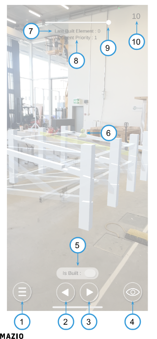
Menu Button: Allows Users to toggle on and off menu options
Previous Step Button: Allows Users to iterate backwards through building order.
Next Step Button: Allows Users to Iterate forward through the building process.
Visibility Menu: Allows Users to toggle on and off various visibility options.
Is Built Button: Allows Users to define elements as completed or not completed.
User Indicator: Indicates at which point in the assembly users are (You == Yellow & Others == Grey)
Last Built Element: Indicates the index of the last element that has been completed.
Current Priority: Indicates what priority group is currently being worked on.
Preview Geometry Slider: Allows the user to adjust the amount of visible geometry in the scene.
Current Element: Indicates at which index in the building process the user is.
Visibility Menu
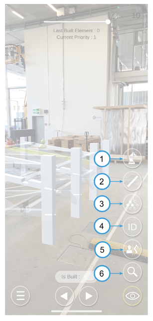
Robot Toggle: Allows User to toggle on and off robots, as well as sets activity for request controls.
Object Measurement Toggle: Displays information for physical measurement verification.
Priority Viewer Toggle: Allows the user to view priority groups individually.
ID Toggle: Displays the ID information for each step in the building plan.
Actor Toggle: Allows the user to toggle on and off actor visualization mode (Human == Yellow & Robot == Blue).
Scroll Search: Allows the user to scroll through and view each object in the assembly.